EasyManua.ls Logo

GE Multilin 850

GE Multilin 850
616 pages
To Next Page IconTo Next Page
To Previous Page IconTo Previous Page
Loading...
CHAPTER 4: SETPOINTS MONITORING
850 FEEDER PROTECTION SYSTEM – INSTRUCTION MANUAL 4–273
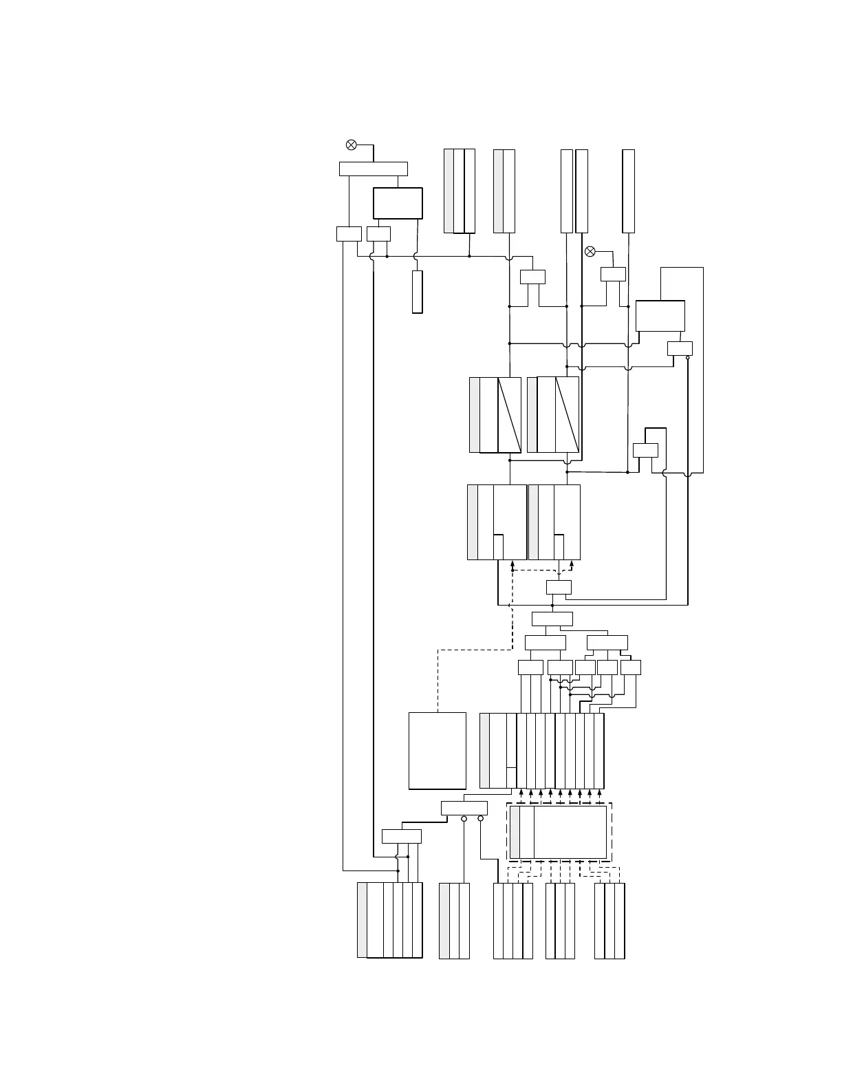
Figure 4-118: Power Factor logic diagram
SETPOINT
BLOCK:
Off=0
AND
SETPOINT
POWER FACTOR 1
FUNCTION:
Disabled
Alarm
Latched Alarm
Configurable
OR
Voltage Inputs
- delta connected
None
PF 1 Switch-In OP
FlexLogic Operands
PF 1 Switch-In
AND AND
Command
RESET
OR
LED: ALARM
VAB
VBC
VCA
Current Inputs
Phase A Current (IA)
Phase B Current (IB)
Phase C Current (IC)
Power Factor of Three
Phases
(delta-connected VTs)
Power Factor of Valid
Phase(s)
(wye-connected VTs)
SETPOINT
POWER FACTOR 1
MINIMUM VOLTAGE :
VAB MINIMUM
RUN
IA > 0.002 xCT
VBC MINIMUM
VCA MINIMUM
IB > 0.002 xCT
IC > 0.002 xCT
AND
OR
SETPOINTS
POWER FACTOR 1
DELAY:
t
DLY
0
SETPOINTS
POWER FACTOR 1
SWITCH-IN:
|PF| < |SWITCH-IN|, both
PF and SWITCH-IN are
lag or lead
RUN
SETPOINTS
POWER FACTOR 1
SWITCH-OUT:
PF passing SWITCH-
OUT
RUN
SETPOINTS
POWER FACTOR 1
DELAY:
t
DLY
0
AND
PF 1 Switch-Out
PF 1 Switch-Out OP
SETPOINTS
OUTPUT RELAYS (3-7):
Do Not Operate, Operate
S
LATCH
Set-
Dominant
R
S
LATCH
Reset-
Dominant
R
OR
OR
OR
LED: PICKUP
OR
Voltage Inputs
- wye connected
VA
VB
VC
VA MINIMUM
VB MINIMUM
VC MINIMUM
AND AND AND
AND
OR
OR
Power 1
(System Setup \
Power Sensing)
Signal Input
SETPOINT
850 Only
894059A3.cdr

Table of Contents

Related product manuals