GEK-113032A W650 Wind Generator Protection System 5-9
5 SETTINGS 5.2 PRODUCT SETUP
5
5.2.4 OSCILLOGRAPHY
5.2.4.1 OVERVIEW
W650 elements allocate 1-Mbyte of memory for storing oscillography records. These oscillography records are stored in
non-volatile memory.
Oscillography records are stored in COMTRADE ASCII - IEEE C37.111-1999 standard format.
The oscillography module is in charge of storing the instantaneous values of the 9 analog signals and the 16 programmable
digital signals at Setpoint > Relay Configuration > Oscillography in fault conditions (OSCILLO TRIGGER signal
activation).
All oscillography records store all analog signals (fixed) plus 16 digital signals (programmable). The order of storage in the
case of analog signals is as follows:
Analog 1 IA channel.
Analog 2 IB channel.
Analog 3 IC channel.
Analog 4 IG channel.
Analog 5 ISG channel.
Analog 6 VA or VAB channel, depending on the selected configuration (Wye or Delta at “Setpoint>System
Setup>General settings>Phase VT Connection”).
Analog 7 VB or VBC channel, depending on the selected configuration (Wye or Delta at “Setpoint>System
Setup>General settings>Phase VT Connection”).
Analog 8 VC or VCA channel, depending on the selected configuration (Wye or Delta at “Setpoint>System
Setup>General settings>Phase VT Connection”).
Analog 9 VN or VX channel, depending on the selected configuration (zero sequence measured, or busbar voltage at
“Setpoint>System Setup>General settings>Auxiliary Voltage”).
The 16 digital channels and the oscillography trigger signal are programmable using the EnerVista 650 Setup software at
Setpoint > Relay configuration > Oscillography. Each digital channel can be associated to a single status or to a logic
status. In this last case, the logic must be configured using the PLC Editor tool, at Setpoint > Logic Configuration inside
EnerVista 650 Setup, and its output must be associated to a virtual output. This virtual output is then associated to a digital
channel. The oscillography trigger signal can be a single status or a configured logic.
5.2.4.2 OSCILLOGRAPHY SETTINGS
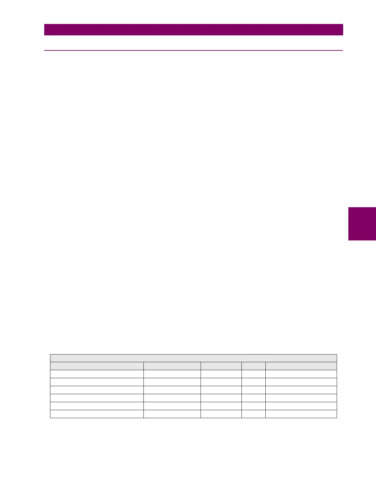
These settings (“Setpoint > Product Setup > Oscillography”) are described in Table 5–12:
Table 5–12: OSCILLOGRAPHY SETTINGS
SETPOINT > PRODUCT SETUP > OSCILLOGRAPHY
Setting Description Name Default Value Step Range
Function Permission Function ENABLED N/A [DISABLED – ENABLED]
Prefault Trigger Position 30 1 % [5 : 95]
Samples per cycle Samples/Cycle 64 N/A [4 – 8 – 16 –32 – 64]
Maximum number of oscillos Max. Number Osc. 4 1 oscillo [1 : 20]
Automatic oscillography overwrite Automatic Overwrite DISABLED N/A [DISABLED – ENABLED]
Snapshot Event generation Snapshot Events ENABLED N/A [DISABLED – ENABLED]