4-4 W650 Wind Generator Protection System GEK-113032A
4.1 ENERVISTA 650 SETUP SOFTWARE INTERFACE 4 HUMAN INTERFACES.
4
4.1.4 COMMUNICATION MENU
To start communicating with the relay go to “Communication>Computer>Computer settings” section in the main
EnerVista 650 Setup menu.
Safety instructions must be followed before connecting the computer to the relay. Safety instructions are detailed in section
1.1.3. Connect the relay ground terminal and the communicating computer to a good grounding. Otherwise, communication
may not be viable, or even, in worst cases, the relay and/or the computer could result damaged by overvoltages.
For on-line working, previously ensure that all relay communication parameters, such as baudrate, slave ModBus address,
etc, match the computer settings.
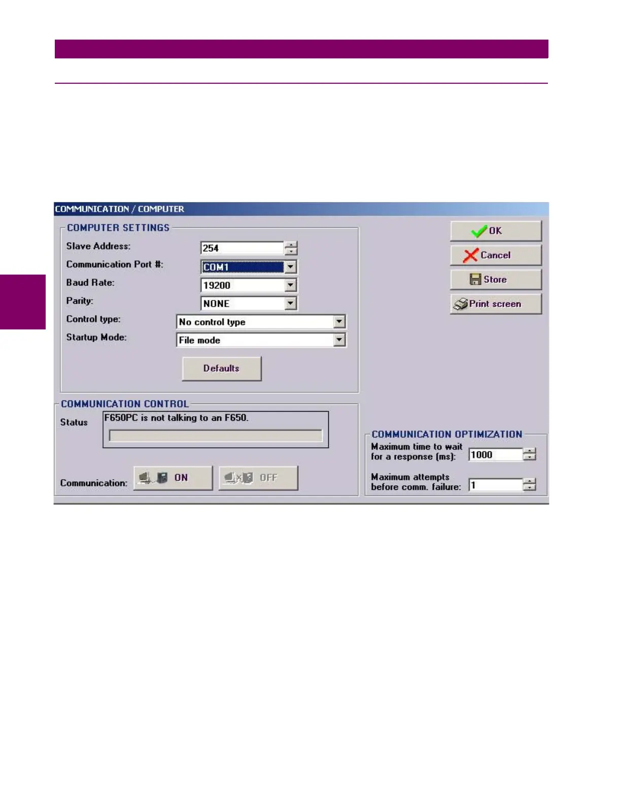
Figure 4–2: COMMUNICATION PARAMETERS MENU
The “Communication > computer” screen is divided in several subsections:
• Computer settings: Main communication parameters for serial communication and control type selection.
• ModBus/TCP Setup (if ModBus /TCP is selected as control type): Communication parameters for ModBus TCP
communication.
• Communication control: Device communication status (communicating or not communicating).
• Communication optimization: allows optimizing the communication time outs and failure establishing.
4.1.4.1 COMPUTER SETTINGS:
Shows the communication parameters necessary in order to establish communication with the unit. Such as slave address,
communication port, baud rate, parity, control type and startup mode.
Baud rate, parity, data bits, stop bits and ModBus slave address for com2 (RS232 front port and second serial port in the
rear communication board) are displayed in the default text logotype main screen.
ModBus Slave Address: ModBus addresses used for serial and Ethernet communication.