5-114 W650 Wind Generator Protection System GEK-113032A
5.8 RELAY CONFIGURATION 5 SETTINGS
5
5.8.4 PROTECTION ELEMENTS
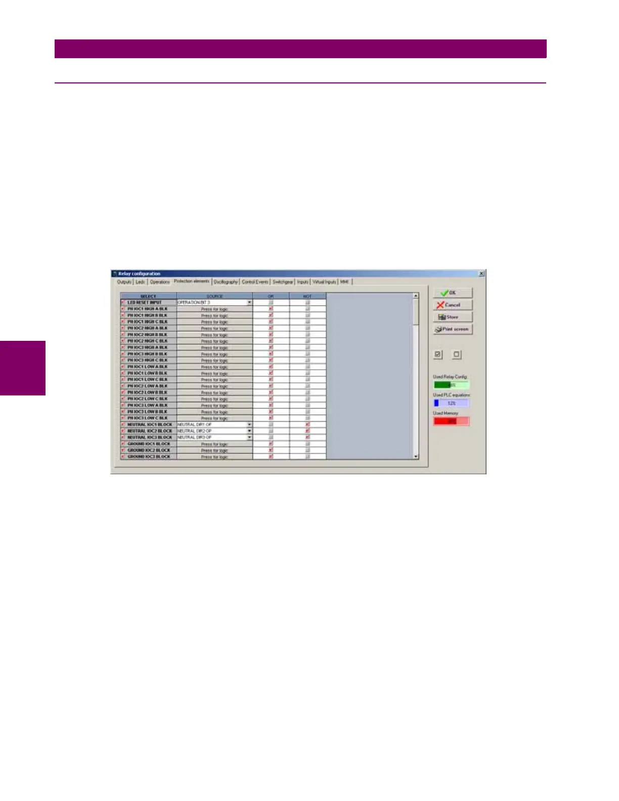
This tab allows assigning operands (logic signals) as inputs to different protection elements. This way, the user assigns
which operands can initiate the autoreclose, block the protection elements, etc. In this screen we can also configure a logic
signal to perform the LED reset by communications.
The settings are as follows:
• Select checkbox enables/disables the selection.
• Source setting defines the operand that performs the function indicated in the SELECT column. NOT setting inverts
the block signal.
• NOT setting for inverting the logic signal.
• OR checkbox to select a group of operands instead of a single one. The relay performs an OR of the signals, and its
output produces the operation.
The following figure shows this screen:
Figure 5–39: PROTECTION ELEMENTS
 Loading...


