GEK-113032A W650 Wind Generator Protection System 5-63
5 SETTINGS 5.4 PROTECTION ELEMENTS
5
5.4.8 VOLTAGE ELEMENTS
The W650 incorporates the following voltage elements:
• Phase undervoltage (27P)
• Phase overvoltage (59P)
• Neutral overvoltage (59NH/59NL)
• Auxiliary overvoltage (59X)
• Auxiliary undervoltage (27X)
• Voltage Unbalance (60)
These protection elements can be used in multiple applications, such as:
Undervoltage protection: for induction motor load types, where a voltage dip can cause an increase of the consumed
current. Element 27P (phase undervoltage) can be used to issue a trip or an alarm.
Transfer Schemes: in the event of an undervoltage condition, we can use the 27P element (phase undervoltage) to send a
signal that will transfer load to another power source.
Undervoltage elements can be set to operate with definite time or with an inverse time curve. If the element is set as
definite time, it will operate when voltage remains under the set value during the set period of time. This period can be set
from 0s to 900.00 s in steps of 10ms.
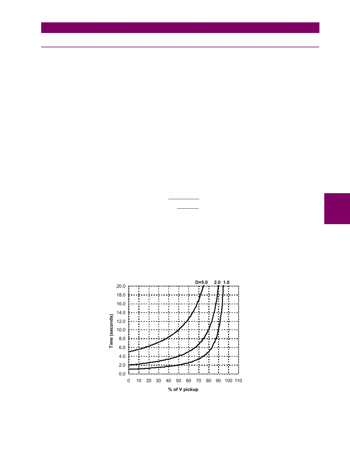
These elements can also be set as inverse time curves. This family of curves is defined by the following formula:
Where:
T = operation time
D = operation time setting (delay)
V = voltage applied to the relay
Vpickup = pickup setting (Pickup level)
Figure 5–13: INVERSE TIME UNDERVOLTAGE CURVES
Vpickup
V
D
T
−
=
1