5-64 W650 Wind Generator Protection System GEK-113032A
5.4 PROTECTION ELEMENTS 5 SETTINGS
5
5.4.8.1 PHASE UNDERVOLTAGE ELEMENT (27P)
This element may be used to give a desired time-delayed operating characteristic versus the applied fundamental voltage
(phase-to-ground or phase-to-phase for wye VT connection, or phase-to phase- for Delta VT connection) or as a Definite
time element. The element resets instantaneously if the applied voltage exceeds the dropout voltage.
The delay setting selects the minimum operating time of the phase undervoltage. The minimum voltage setting selects the
operating voltage below which the element is blocked (a setting of "0" will allow a dead source to be considered a fault
condition.
This element generates independent pickup and trip signals per phase, and general pickup and trip signals for the element.
These last signals can be selected, by means of the operation logic setting, to be an OR (any phase signal) or an AND (all
phase signals).
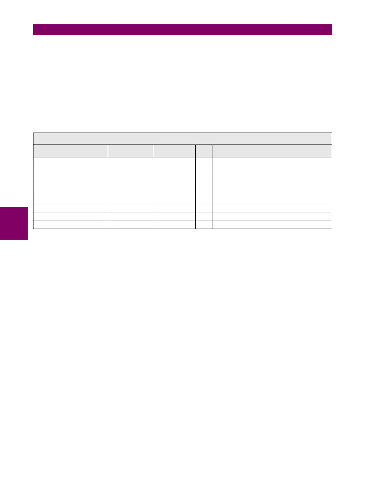
Table 5–61: 27P ELEMENT SETTINGS
Phase undervoltage element settings are:
Function Permission (Function):This setting indicates whether the phase undervoltage element is enabled or disabled.
Input mode (Mode): This setting allows selecting operation for phase-to-phase or phase-to-ground voltage,
depending on the selected setting.
Pickup Level: This is the voltage threshold below which the undervoltage element will operate.
Curve Shape (Curve): Undervoltage elements can be set to operate with definite time or with an inverse time
curve. Elements set as definite time operate when the voltage value remains under the
pickup setting during the set time. If inverse time is selected, the element will operate
according to the previously described inverse time curve.
Time Dial (Delay): Setting of the Protection element operation time.
Minimum voltage Threshold (Minimum Voltage):Voltage setting under which the undervoltage element is inhibited, in
order not to operate in dead line cases.
Operation logic (Logic): This setting allows the element operation logic selection:
ANY PHASE The element will operate under an undervoltage condition in any of the
three phases.
TWO PHASES The element will operate under an undervoltage condition in at least two
phases.
ALL PHASES The element will operate under an undervoltage condition in the three
phases.
Supervision by breaker status (Supervised by 52):This setting allows inhibiting the undervoltage element if the breaker
is open breaker. In case this setting is enabled, the undervoltage element will be
supervised by the breaker status. Otherwise, the element will operate independently of
the breaker status.
Snapshot Events: The snapshot event setting enables or disables the snapshot event generation for this
element.
SETPOINT > PROTECTION ELEMENTS > VOLTAGE ELEMENTS > PHASE UV >
PHASE UV 1> PHASE UV 2 > PHASE UV 3 > PHASE UV 4
SETTING DESCRIPTION NAME DEFAULT
VALUE
STEP RANGE
Function permission Function DISABLED N/A [DISABLED – ENABLED]
Input mode Mode PHASE-PHASE N/A [PHASE-PHASE, PHASE-GROUND]
Pickup Level Pickup Level 50 1 V [3 : 850]
Curve shape Curve DEFINITE TIME N/A [DEFINITE TIME – INVERSE TIME]
Time Dial Delay 10.00 0.01 s [0.00 : 900.00]
Minimum Voltage Threshold Minimum Voltage 0 1 V [0 : 850]
Operation logic Logic ANY PHASE N/A [ANY PHASE – TWO PHASES – ALL PHASES]
Supervision by breaker status Supervised by 52 DISABLED N/A [DISABLED – ENABLED]
Snapshot Event generation Snapshot Events ENABLED N/A [DISABLED – ENABLED]
 Loading...


