GEK-113032A W650 Wind Generator Protection System 5-69
5 SETTINGS 5.4 PROTECTION ELEMENTS
5
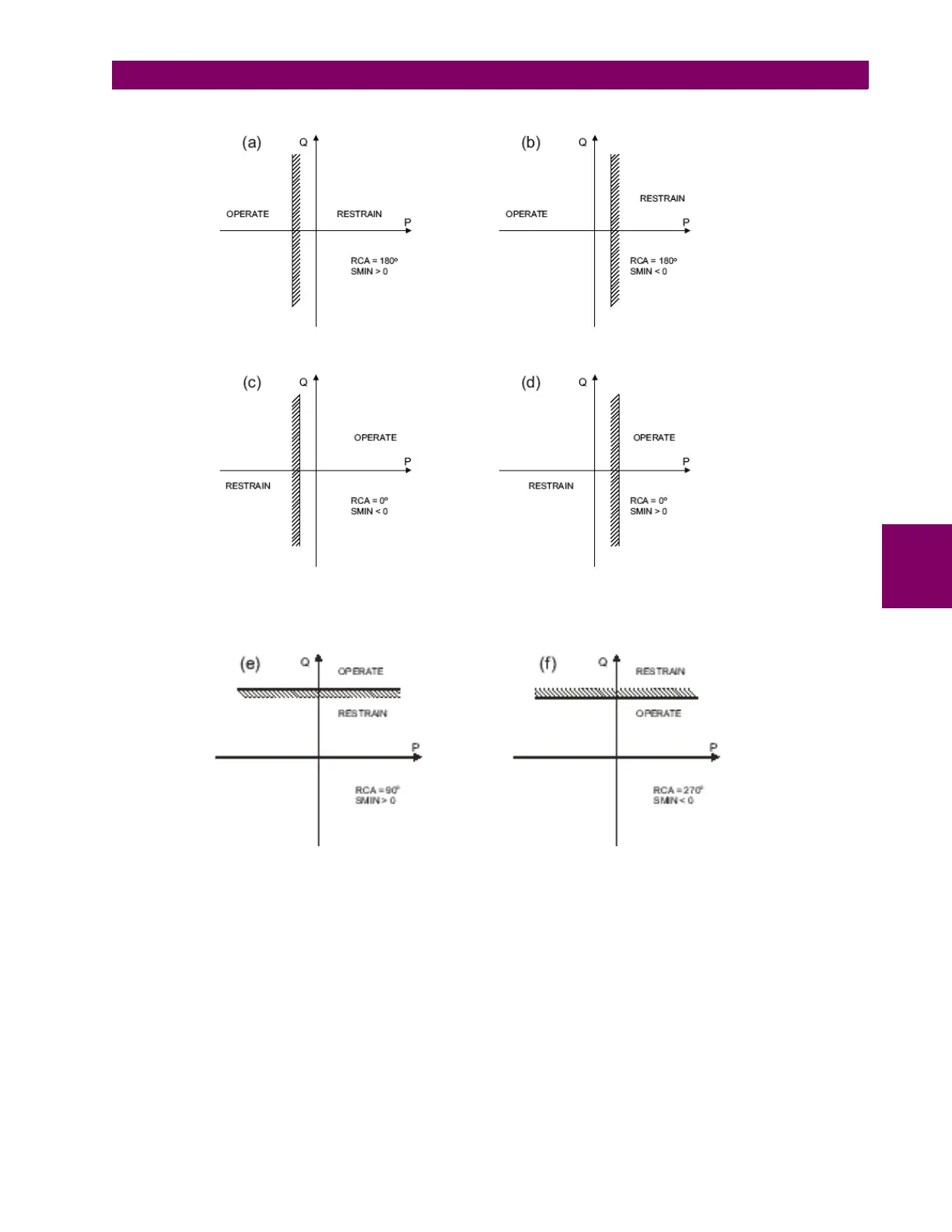
Figures (a, b, c, d, e, f) below shows settings for different power applications.
Figure 5–15: DIRECTIONAL POWER ELEMENT SAMPLE APPLICATIONS
By adding 90º to the angles shown on figures a, b, c and d, the represented elements would be similar but with Reactive
Power instead of Active Power.
Any other angle would provide a mixed Protection Between Active and Reactive power.