4-22 W650 Wind Generator Protection System GEK-113032A
4.1 ENERVISTA 650 SETUP SOFTWARE INTERFACE 4 HUMAN INTERFACES.
4
4.1.8.5 INPUT/OUTPUTS
Section that contains the settings for all input and output boards and the Force Outputs and Virtual inputs activation tools.
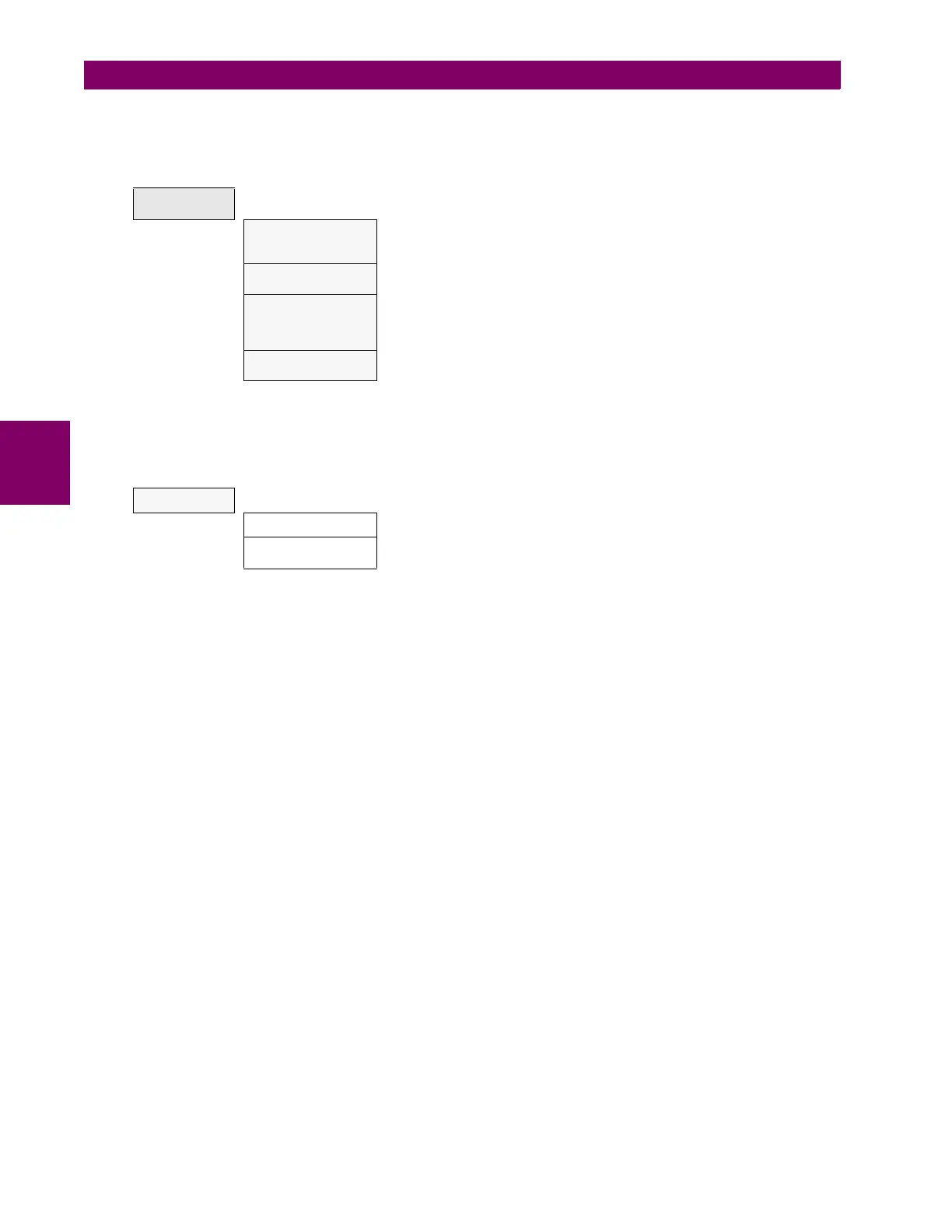
Table 4–12: GENERAL OVERVIEW OF “INPUTS/OUTPUTS” SETTINGS MENU.
Options enabled only in On-line mode are marked as (*). Options enabled only in Off-line mode are marked as (**)
This section shows the settings related to inputs and outputs for the different boards available in W650 (F, G).
Table 4–13: GENERAL OVERVIEW OF “INPUTS/OUTPUTS>CONTACT I/O” SETTINGS MENU.
INPUTS/
OUTPUTS
Contact I/O
Inputs and outputs settings for all boards in W650. The I/O settings
configuration can only be performed through EnerVista 650 Setup, not
HMI available.
Force Outputs (*)
This menu allows activating each contact output in the relay, to facilitate
maintenance testing. On line mode only.
Virtual Inputs (*)
This menu allows operating virtual inputs. These variables are used as
inputs to logic schemes configured in the relay. Virtual inputs can be
operated in a latched mode (32 latched virtual inputs) or in Self-reset
mode (32 self reset virtual inputs).
Remote Comms.
This menu allows configuring remote inputs coming from other devices
through GSSE messages.
CONTACT I/O
Board F Board located in first slot, always connected.
Board G
Board located in second slot, depends on model definition. If model is
type G0 there is no board in second slot.