PRINTED IN U.S.A. 27 913287/BP0808
cooling system.
E - Alternator Lamp: This lamp indicates the condi-
tion of the electrical charging system. During nor-
mal operation, this lamp should be off. If the
charge rate is too high or too low, this lamp will
come on.
F - Air Cleaner Restriction Lamp: If this lamp
comes on, the air cleaner should be checked for a
clogged inlet or filter element.
G - Transmission Oil Temperature Lamp: This
lamp indicates whether the transmission oil is at
the proper temperature. During normal operation
this lamp should be off.
IMPORTANT: If the temperature lamp comes on
during normal operation, a problem may exist in
the transmission system. Stop the machine as
soon as possible and investigate the cause of the
problem!
H - Accumulator Charge Lamp: When the operat-
ing pressure is too low, this lamp will come on. A
low pressure indication requires recharging the
accumulator.
I - Low Fuel Lamp: This lamp indicates a low fuel
situation. When it first comes on, there is approx-
imately 2.5 gals. (9.5 L) of fuel remaining. The
fuel tank should be filled as soon as possible.
J - Hydraulic Oil Filter Lamp: If this lamp comes
on, it indicates that the filter element should be
checked for possible replacement.
RIGHT SIDE PANEL
These controls and indicators are used to position the
frame, boom, and attachment. Graphic symbols on the
side panel illustrate the control actions.
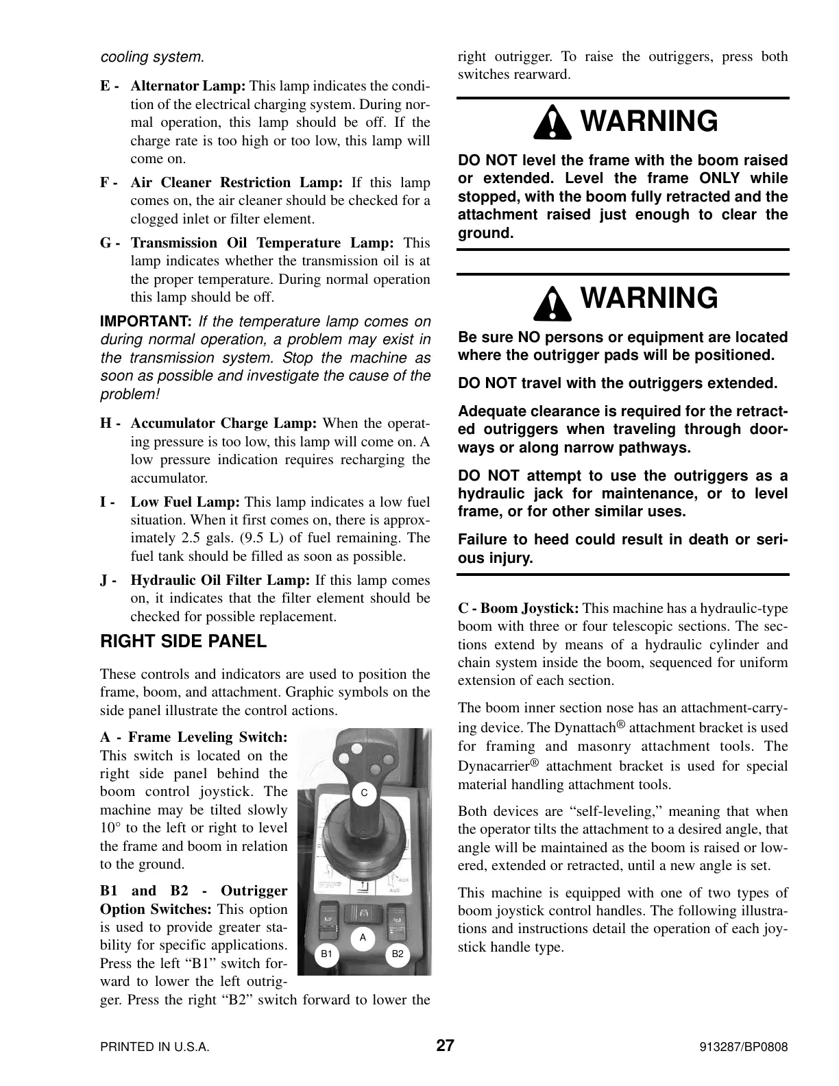
A - Frame Leveling Switch:
This switch is located on the
right side panel behind the
boom control joystick. The
machine may be tilted slowly
10° to the left or right to level
the frame and boom in relation
to the ground.
B1 and B2 - Outrigger
Option Switches: This option
is used to provide greater sta-
bility for specific applications.
Press the left “B1” switch for-
ward to lower the left outrig-
ger. Press the right “B2” switch forward to lower the
right outrigger. To raise the outriggers, press both
switches rearward.
C - Boom Joystick: This machine has a hydraulic-type
boom with three or four telescopic sections. The sec-
tions extend by means of a hydraulic cylinder and
chain system inside the boom, sequenced for uniform
extension of each section.
The boom inner section nose has an attachment-carry-
ing device. The Dynattach
®
attachment bracket is used
for framing and masonry attachment tools. The
Dynacarrier
®
attachment bracket is used for special
material handling attachment tools.
Both devices are “self-leveling,” meaning that when
the operator tilts the attachment to a desired angle, that
angle will be maintained as the boom is raised or low-
ered, extended or retracted, until a new angle is set.
This machine is equipped with one of two types of
boom joystick control handles. The following illustra-
tions and instructions detail the operation of each joy-
stick handle type.
WARNING
DO NOT level the frame with the boom raised
or extended. Level the frame ONLY while
stopped, with the boom fully retracted and the
attachment raised just enough to clear the
ground.
WARNING
Be sure NO persons or equipment are located
where the outrigger pads will be positioned.
DO NOT travel with the outriggers extended.
Adequate clearance is required for the retract-
ed outriggers when traveling through door-
ways or along narrow pathways.
DO NOT attempt to use the outriggers as a
hydraulic jack for maintenance, or to level
frame, or for other similar uses.
Failure to heed could result in death or seri-
ous injury.
C
B1 B2
A
Courtesy of Crane.Market
 Loading...