PRINTED IN U.S.A. 29 913287/BP0808
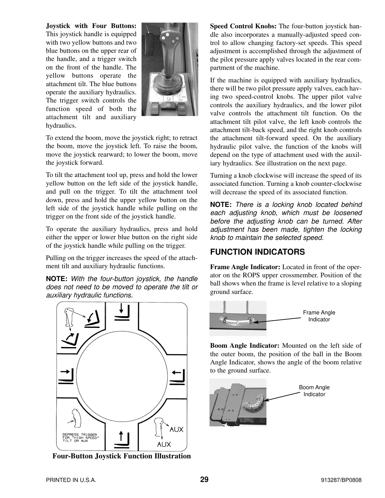
Joystick with Four Buttons:
This joystick handle is equipped
with two yellow buttons and two
blue buttons on the upper rear of
the handle, and a trigger switch
on the front of the handle. The
yellow buttons operate the
attachment tilt. The blue buttons
operate the auxiliary hydraulics.
The trigger switch controls the
function speed of both the
attachment tilt and auxiliary
hydraulics.
To extend the boom, move the joystick right; to retract
the boom, move the joystick left. To raise the boom,
move the joystick rearward; to lower the boom, move
the joystick forward.
To tilt the attachment tool up, press and hold the lower
yellow button on the left side of the joystick handle,
and pull on the trigger. To tilt the attachment tool
down, press and hold the upper yellow button on the
left side of the joystick handle while pulling on the
trigger on the front side of the joystick handle.
To operate the auxiliary hydraulics, press and hold
either the upper or lower blue button on the right side
of the joystick handle while pulling on the trigger.
Pulling on the trigger increases the speed of the attach-
ment tilt and auxiliary hydraulic functions.
NOTE: With the four-button joystick, the handle
does not need to be moved to operate the tilt or
auxiliary hydraulic functions.
Speed Control Knobs: The four-button joystick han-
dle also incorporates a manually-adjusted speed con-
trol to allow changing factory-set speeds. This speed
adjustment is accomplished through the adjustment of
the pilot pressure apply valves located in the rear com-
partment of the machine.
If the machine is equipped with auxiliary hydraulics,
there will be two pilot pressure apply valves, each hav-
ing two speed-control knobs. The upper pilot valve
controls the auxiliary hydraulics, and the lower pilot
valve controls the attachment tilt function. On the
attachment tilt pilot valve, the left knob controls the
attachment tilt-back speed, and the right knob controls
the attachment tilt-forward speed. On the auxiliary
hydraulic pilot valve, the function of the knobs will
depend on the type of attachment used with the auxil-
iary hydraulics. See illustration on the next page.
Turning a knob clockwise will increase the speed of its
associated function. Turning a knob counter-clockwise
will decrease the speed of its associated function.
NOTE: There is a locking knob located behind
each adjusting knob, which must be loosened
before the adjusting knob can be turned. After
adjustment has been made, tighten the locking
knob to maintain the selected speed.
FUNCTION INDICATORS
Frame Angle Indicator: Located in front of the oper-
ator on the ROPS upper crossmember. Position of the
ball shows when the frame is level relative to a sloping
ground surface.
Boom Angle Indicator: Mounted on the left side of
the outer boom, the position of the ball in the Boom
Angle Indicator, shows the angle of the boom relative
to the ground surface.
Four-Button Joystick Function Illustration
Boom Angle
Indicator
Frame Angle
Indicator
Courtesy of Crane.Market
 Loading...