Rev. 00 03/19
38
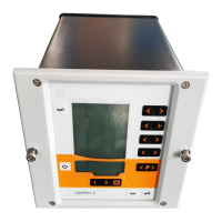
Start-up OptiStar 4.0 (CG24-CP)
Hardware
The OptiStar control units are connected to the central PLC control unit
via 4 pin CAN bus cables. The last bus client is fitted with a terminal plug
with terminal resistor in order to terminate the network correctly. A
maximum of up to 127 MultiStar Control units can be operated in a
network.
CAN bus participant no. 127
(max)
fig.
: CAN bus – connections
1 PLC control with CAN bus
CAN bus cable – plug assignment
fig.
: CAN bus cable