Rev. 00 03/19
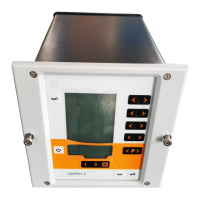
OptiStar 4.0 (CG24-CP) Operation
49
3. The correction factor number is shown in the display A1 with a C
placed in front
4. Set the corresponding correction value with the T3 or T4 key.
– The value of the adjusted correction factor appears on
corresponding display A2
5. Scroll to the next or previous correction factor with the T1 or T2 key
6. Select correction values according to the following table
Powder hose correction value (%)
Daily correction value (%)
Transport air offset (Nm³/h)
Pump operating frequency (Hz)
Pinch valves set pressure Conveying mode
(bar)
Pinch valves set pressure Cleaning mode (bar)
Permissible compressed air consumption
(mbar/bar) = Threshold value for error message
H89
1)
The adjustment range applies to the half cycle time.
2)
Depending on the unit set, airflows are displayed and entered in
Nm³/h or scfm.
3)
Do not change!
4)
Use only if blockings occur.
 Loading...