Weld334m - User’s manual
17
3.1.3
Power consumption
Power used is dependent on the type of application carried out on the machine.
Table below lists the minimum power to apply to the control device in its full configuration,
depending on the type of power supply being used.
Consumption
Power feeder Power supply type 24V Internal 24V External
F350/370 Vac Transformer (recommended): 110VA 62VA
F350/370 Vdc Power feeder (recommended): 80W 45W
3.2
Use of 24V - I/O
To make use of 24V supply of I/O, certain rules are to be observed. These rules depend on
the type of application used on the machine.
The Weld334m is supplied by GF WELDING
in a standard configuration; 24V = make
jumpers between pin 5 and pin 6 (see figure below).
Faston
Power supply
External sync
1
2
3
4
5
6
7 0V
8 0V
PS
PWR
SYNC.
1
2
3
4
P20
Weld334
*
+24
0V
I/O
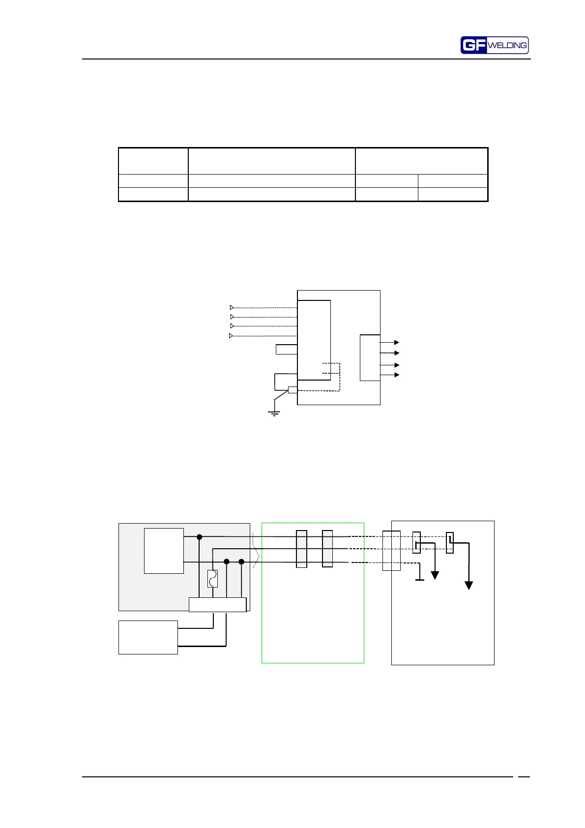
3.2.1
Selecting 24V – internal or external
24V supply for I/O input is distributed in such a way to have two internal separate lines.
These lines are alternate between one another:
•
One line for external 24V (24VE), whose input is located on pin 6 and pin 7 of PS
•
One for internal 24V (24VI) which, from the power feeder, is connected directly to
bus connectors JP2/3/4/5/6 (see figure 1).
Internal power
feeder
PS
BUS W334m
External power
feeder
24VE
5 6 7 8
24VI
0V
24VI
24VE
0V
JP2
JP3
J1
J2
24V I/O
24V
PULS.Com.
IMP.
1
2
3
1
2
3
IOB
module
P7
Figure 1
The modules using 24Vdc supply have 2 jumpers: J1 for 24V of I/O and J2 for 24V supply
used for the pulse control or the servovalve. These jumpers allow +24V supply to be set
toward the internal power feeder or toward an external+24V supply.
Each module is factory-calibrated (standard calibration) and calibration value is shown on
the layout page in the chapter concerning each module.
Figure 1 gives an example of setting for these 2 jumpers.