Weld334m - User’s manual
F364-SEV and F385-SEV Proportional Servovalve Modules
33
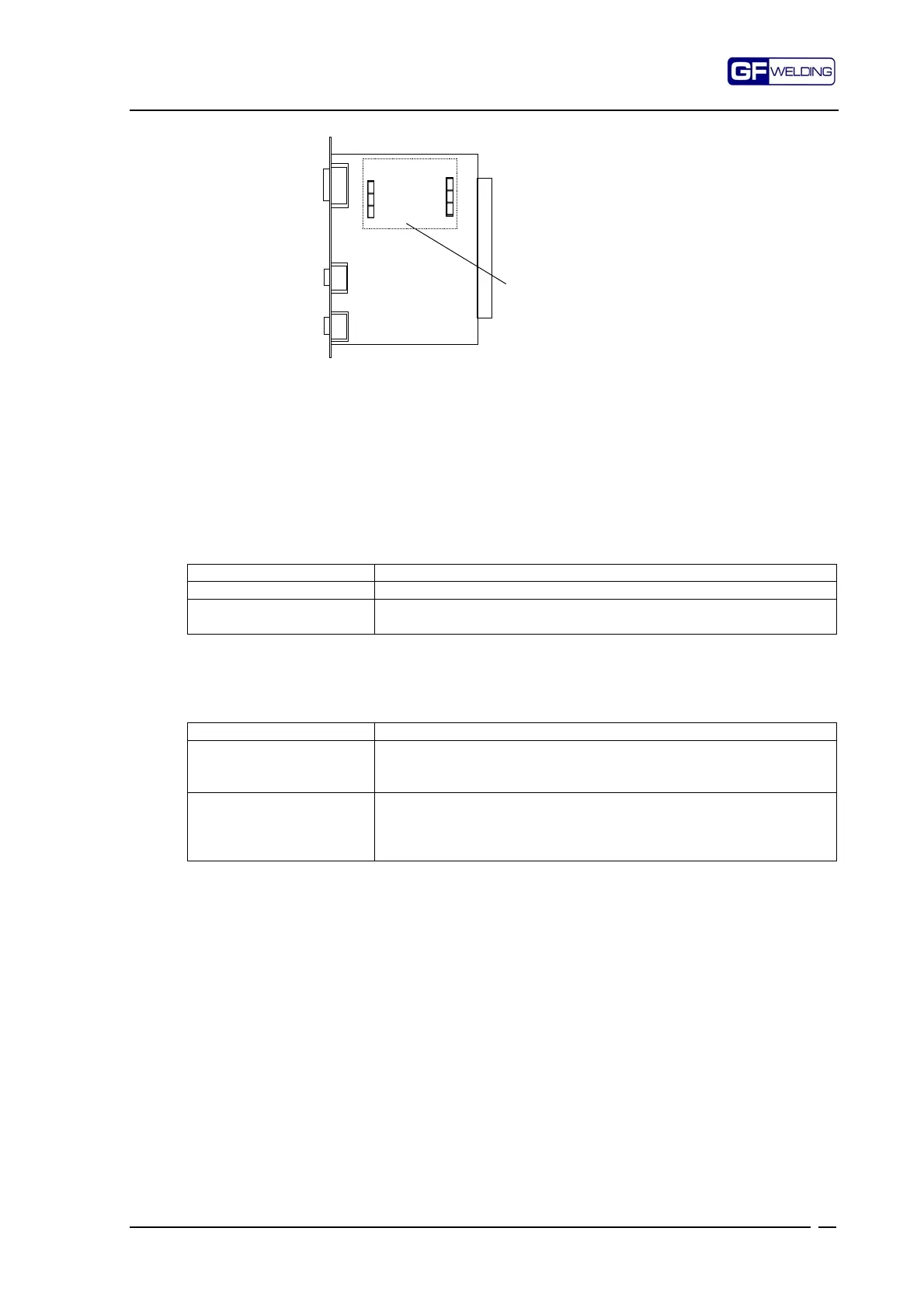
Fixing of the module is ensured by the tight fit of the two connectors J1-J3
Make sure that the module is properly fitted into the card.
(For the SEV pin-out refer to the chapter “P2. Description of the signals for the Solenoid
valve and the TFE”).
7.2.1
Jumper function on connector J4
For further information consult the chapter “Use of 24V I/O”
Pins connected Description
1-2 Power supply to SEV from internal 24Vdc
2-3 Power su
l
to SEV indirect from internal 24Vdc or from
external 24Vdc
7.2.2
Jumper function on connector J5
Pins connected Description
1-2
(Default)
24Vdc limiter SEV
ower su
l
OFF. Position re
uired when
stabilized 24Vdc is available (e.g.: with PSM type F370)
2-3
(Only for F364, for
compatibility with old
module F368)
24Vdc limiter SEV
ower su
l
ON. Position re
uired when
non-stabilized 24Vdc is available (e.g.: with PSM type F367)
Mounting position of the
F385-SVV Module
F364-SEV Module
P2
P3
P4
J3 J1
F353-ADC