Weld334m - User’s manual
F351-BUS Interconnection card
23
Code:33035100
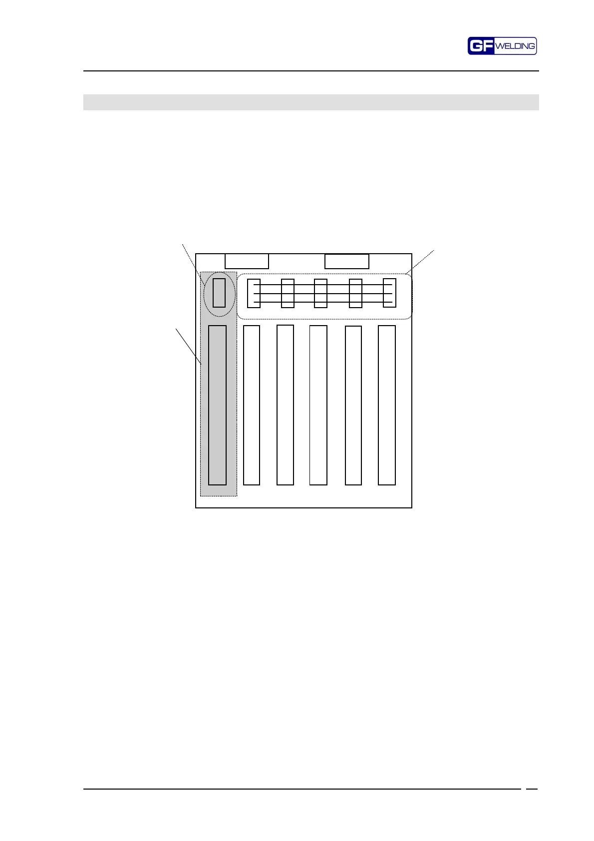
4. F351-BUS Interconnection card
BUS interconnection card for signals and power supply.
J2 connector takes 24V supply for the I/O power supply.
J1 connector takes 5V supply for the cards and +V for programming unit HHT.
JP1 connector is used to power the programming keycard (via CPU).
The connectors JP2, 3, 4, 5, 6 distribute 24VI and 24VE supply for the I/O points.
Connectors P1...6 form the digital BUS.
P1 P2 P3 P4 P5 P6
JP1 JP2 JP3 JP4 JP5 JP6
Bus 24V I/O
Power supply
HHT4300
J1
J2
F384 CPU
F351 BUS
24VI
24VE
0V
The position JP1-P1 is typical for the CPU card, all the remaining positions are available for
the control device configuration.
The BUS module needs no preset.