Weld334m - User’s manual
F356-IOE I/O Expansion Card
41
Code:33035600
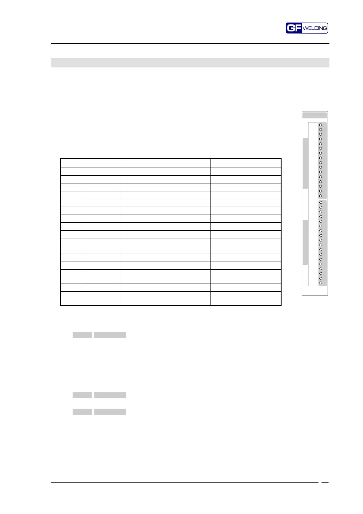
10. F356-IOE I/O Expansion Card
This card houses two terminal type connectors - a 18-way connector (P24) and a 16-way
connector (P23) – for the connection to the field. They support 18 off 14V inputs (20/30V -
10mA) and 16 off 24V - 0.3A inputs, four of which (dedicated to the welding solenoid
valves) are protected against the simultaneous clamping of guns through a relay
interlocking.
All outputs are protected against short circuit.
10.1
P23 . Description of output signals
16-way, 3.5 mm pitch linear connector for disconnectable terminals
Pin Signal Description Type
1 WALLSTA Stepper A pre-alarm Electrodes wear function
2 WALLSTB Stepper B pre-alarm Electrodes wear function
3 ALLSTA Stepper A alarm Electrodes wear function
4 ALLSTB Stepper B alarm Electrodes wear function
5 RICHRAV Request for dressing Electrodes wear function
6 RICHEL Request for electrodes change Electrodes wear function
7 ALARM1 Diagnostic alarm Welding diagnostics
8 ALARM2 Hardware alarm Machine fault
9 UNDCURR Minimum current alarm Welding diagnostics
10 OVRCURR Maximum alarm current Welding diagnostics
11 READY Ready Status
12 STATUS Weld Yes/No Status
13 EVSA Channel A welding Solen. Valve Solen. Valve control
14 EVASA Channel A addit. Opening solen.
Valve
Solen. Valve control
15 EVSB Channel B welding solen. Valve Solen. Valve control
16 EVASB Channel B addit. Opening solen.
Valve
Solen. Valve control
P23 . Functional description of signals
Pin Signal Function
1 WALLSTA
Stepper A pre-alarm. Active at +24V.
This output is activated as a function of the programming of
the stepper concerned.
It does not shut down the cycle. It is an indication that the
counter is approaching the Stepper Stop threshold.
Consult the programming manual for the activation of this
function.
The message is memorised in the alarm history.
2 WALLSTB
Same as WALLSTA, but for channel B.
3 ALLSTA
Stepper A alarm. Active at +24V.
This output is activated as a function of the programming of
the stepper concerned.
Consult the programming manual for the activation/reset of
this function. In the machine shutdown condition, the signal
can be reset only by setting the counter of the relevant
stepper to zero. This can be made via the RESASA (P24-7)
input, or through the software reset in the Stepper menu.
F356-IOE
1
2
3
4
5
6
7
8
9
10
11
12
13
14
15
16
1
2
3
4
5
6
7
8
9
10
11
12
13
14
15
16
17
18
P
2
4
I
N
P
U
T
S
P
2
3
O
U
T
P
U
T
S