Weld334m - User’s manual
F353-ADC Analogue Card
27
Code :33035300
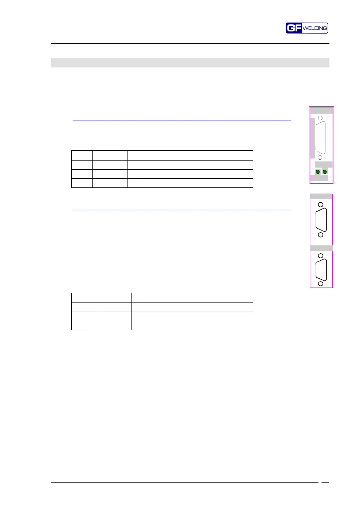
6. F353-ADC Analogue Card
This card includes 3 analogue inputs for acquiring signals from connectors P2 - P3 - P4 and
the internal arrangement for housing the SEV module (optional extra) with output on the
P2 for the electrode pressure adjustment (proportional solenoid valve).
6.1
P3 e P4 . Description of the analogue inputs
P3 - TV - 9-way, Sub-d plug connector
Input for acquiring analogue signals (optional extra); Generally it is not used
and is reserved for special applications
Sensitivity: 36V max.
Pin Signal Description
7 TV+ Positive signal
8 TV - Negative signal
9 TVsch Cable screening
P4 - TA - 9-way, Sub-d plug connector
Input for acquiring analogue signals.
It is used for connecting the current sensor.
The acquisition of this signal (when welding current is constant), permits the
real-time check on the current trend during the welding pulse.
Input is so arranged to accept a 150mV/kA ±3% Rowgowsky type sensor
with 20-25ohm internal resistance.
Sensitivity: adjustable.
Facility to connect up to a maximum of 6 sensors in series.
For correct use, see setting parameters indicated in the programming
manual.
For the connections, refer to relevant application diagrams.
Pin Signal Description
1 TAsch Cable screening
4 TA+ Positive signal
5 TA- Negative signal
NOTE: The control device can be operated even if the F353-ADC card is not installed, but,
in this case, only the «normal» welding mode is allowed.
This type of operation however is detrimental to the processing quality and it has
now been superseded.
P
3
P
4
ANALOG IN
CURR.SENSOR
F353-ADC
STSERV
ENSERV
P
2
S
E
R
V
O
V
A
L
V
E