Weld334m - User’s manual
F386 Ethernet 100Base-T and CANbus module
54
1
2
3
4
5
6
7
8
P10 connector
pinning (front
view)
12.2.3
P10 Ethernet 100Base-T connector
RJ45 8-pole female shielded type MDI configuration
Pin Signal Function
1 TD+ Positive data transmission
2 TD- Negative data transmission
3 RD+ Positive data reception
4- Not used
5- Not used
6 RD- Negative data reception
7- Not used
8- Not used
Shield PE
12.2.4
Ethernet status LED’s
LED Colour Meaning
LAN Green ON when data transmission is in progress
LINK Yellow OFF when there is a line fault
12.3
Ethernet connection cable
12.3.1
Features
•
Cable type (100Base-T): Category 5 or 5e UTP up to 100m.
•
Cable type (10Base-T): Category 3, 4, 5 or 5e UTP up to 100m.
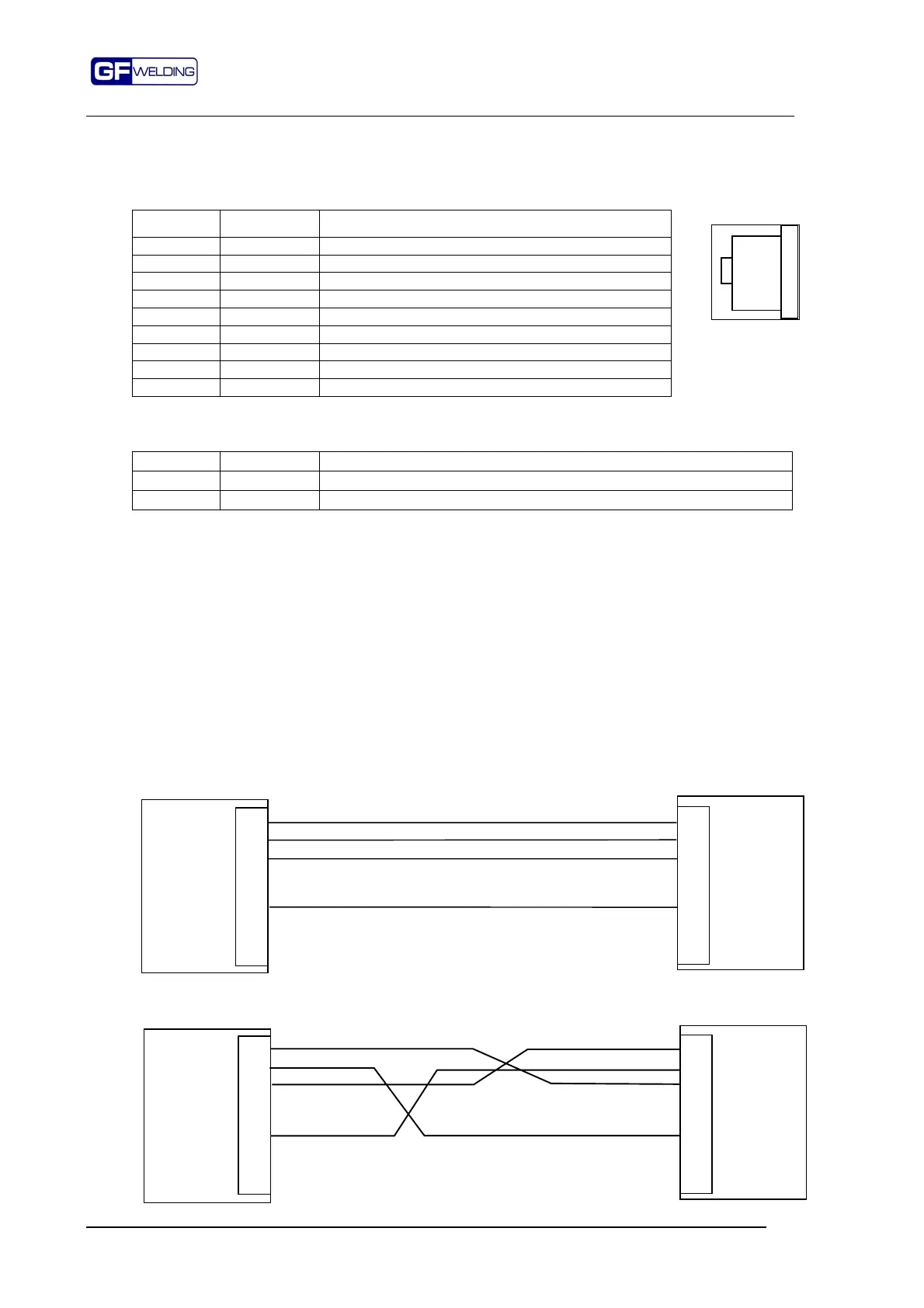
12.3.2
Connection type
The RJ45 connection layout depends on the type of connection of the used HUB input port.
It can be a HUB with MDI connection or a HUB with MDI-X connection.
Before making the cable please check the port type on the HUB.
12.3.2.1
Connection for HUB with MDI-X port
In this case the connection between the two connectors is "Pin to Pin".
12.3.2.2
Connection for remote HUB with MDI port
In the connection with MDI port the signals are "crossed".
1
2
3
4
5
6
7
8
F386-ETH
Remote
HUB with
MDI-X type
port
1
2
3
4
5
6
7
8
1
2
3
4
5
6
7
8
F386-ETH
Remote
HUB with
MDI type
port
1
2
3
4
5
6
7
8