Weld334m - User’s manual
F353-ADC Analogue Card
28
6.2
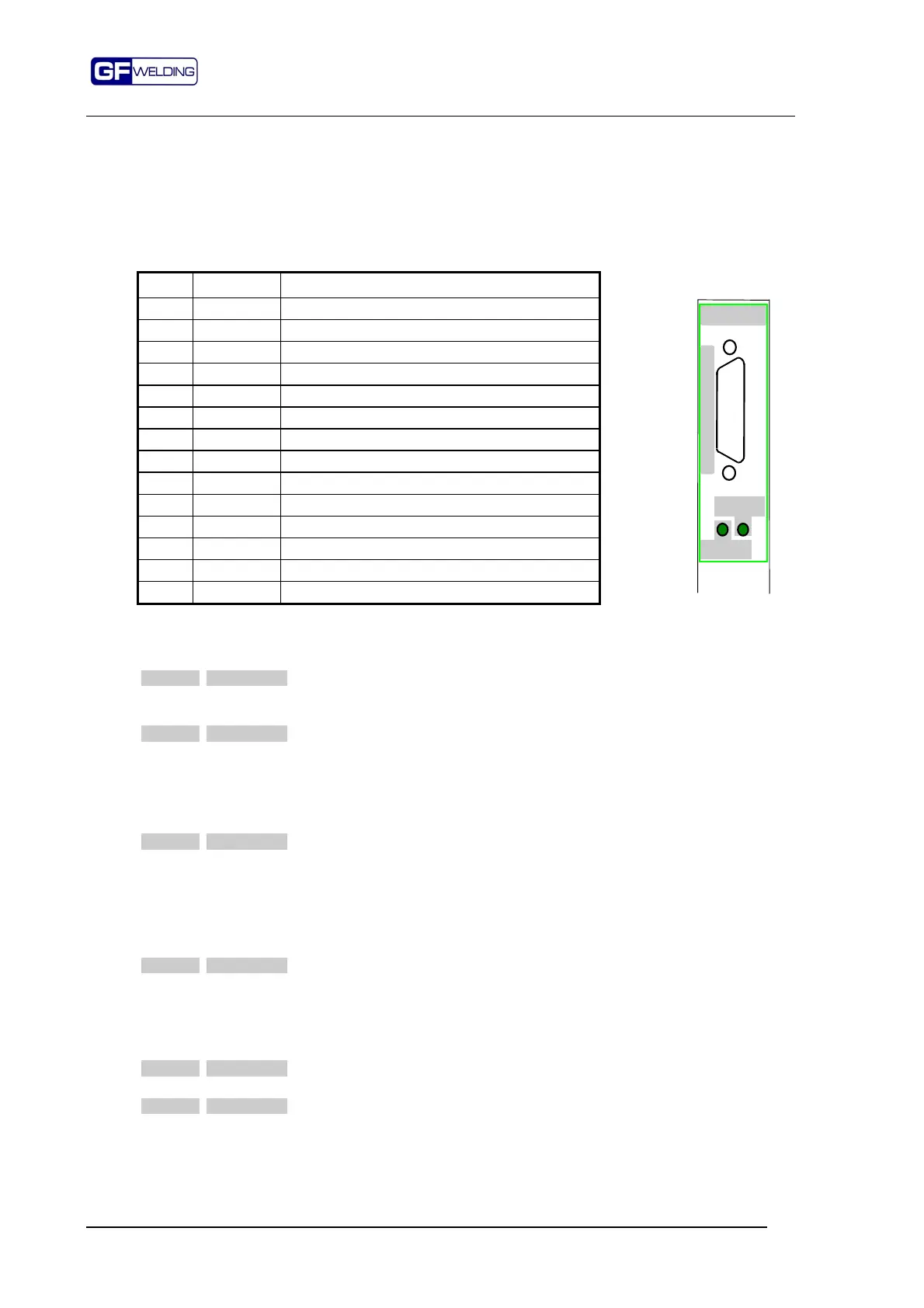
P2 . Description of the signals for the Solenoid valve and the TFE
The two green LED indicators are for the proportional solenoid valve and their function is
the following:
ENSERV
: = illuminated when the relevant output on P2 is active
STSERV
: = illuminated when the signal is present on the input.
15-way, Sub-d socket connector
Pin Signal Description
1 TFEsch Screening of analogue voltage input
2 TFE- Analogue voltage input
3 VServ- 0V voltage output for solenoid valve
4 IServ+ 4-20mA current output for solenoid valve
5 Res2 Reserved
6 STSERV Servovalve status input
7 0V Solenoid valve power supply
8 24SV Solenoid valve power supply
9 TFE+ Analogue voltage input
10 VServ+ 0-10V voltage output for solenoid valve
11 Schield Screening for ISERV or VSERV signal
12 IServ- 0V current output for solenoid valve
14 Res1 Reserved
15 ENSERV Solenoid valve Enable Output
P2 . Functional description of signals
Pin Signal Function
1,2,9 TFE
Analogue voltage acquisition channel.
This input can be used for receiving the indication of the electrodes force
through a dedicated transducer.
4,12 ISERV
Current output. Operating range from 4 to 20 mA.
Signal for piloting a current type solenoid valve.
The valve adjusts pressure on the electrodes as a function of this signal, 20mA
correspond to 100% of the pressure value which has been calibrated on the
proportional valve.
Load resistor:470
Ω
(range: from 200 to 600
Ω)
3,10 VSERV
Voltage output. Operating range from 0 to 10V.
Signal for piloting a voltage type solenoid valve.
The valve adjusts pressure on the electrodes as a function of this signal, 10V
correspond to 100% of the pressure value calibrated on the proportional valve.
The output is protected against overcurrent and short circuit. In case of tripping
of the protective device, outgoing voltage falls to 0 Volt.
Typical resistive load: 10K
Ω
6 STSERV
Input. Electrodes pressure OK.
The logic condition 0V or 24V can be defined in the Setup stage.
Before welding, the control device waits for this signal produced by the solenoid
valve: if the logic condition is TRUE (24V), the control device gives the welding
pulse, if it is FALSE (0V), the welding sequence stays idle with the electrodes
closed.
7 0V
0V solenoid valve power supply.
8 24SV
Solenoid valve power supply
Power supply to the solenoid valve is monitored with a voltage value: if it falls
below 22.5V (5% of 24V), the ENSERV enable signal of the solenoid valve is not
activated.
F353-ADC
STSERV
ENSERV
P
2
S
E
R
V
O
V
A
L
V
E