Weld334m - User’s manual
18
24V I/O can be managed in the following ways:
◊
Direct
: 24VI supply with pins 5 - 6 of PS being free (see paragraph
3.2.2 figure
a
)
J1 connector: jumpers of I/O and ADC cards to be made in position 1-2.
◊
Indirect
: 24VI supply with pins 5 and 6 of the PS: make jumpers or cut them out
from a contact (see paragraph
3.2.2 figure
b
).
24VI supply, which in this way can be cut out from the outside (enabled/disabled),
is re-closed on 24VE line.
◊
External
: with external 24V supply connected to pin 6 and pin 7 of the PS (see
paragraph
3.2.2 figures
c
and
d
)
.
Summary Table of 24V I/O jumpers of cards
24V Selection J1 J2*
Internal 1-2 1-2
Internal indirect 2-3 1-2
External 2-3 2-3
* Where present
3.2.2
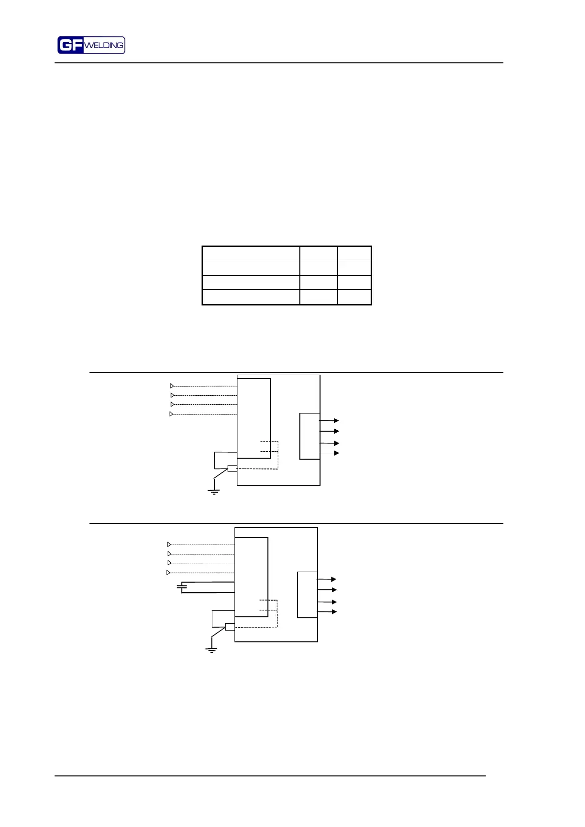
24V connections for discrete I/O
Figure a: Use of +24VI supply in direct way
Faston
Weld334m
1
2
3
4
5
6
7 0V
8 0V
PS
PWR
SYNC.
Power supply
External sync
1
2
3
4
P20
*
+24
0V
I/O
Figure b: Use of +24VI in indirect way
Faston
Power supply
External sync
1
2
3
4
5
6
7 0V
8 0V
PS
PWR
SYNC.
1
2
3
4
P20
Weld334m
*
+24
0V
I/O
24VI is cut off on the PS between pin 5 and pin 6. Thus, 24V supply of I/Os can be enabled and
disabled independently of the control device.