Weld334m - User’s manual
F386 Ethernet 100Base-T and CANbus module
53
12. F386 Ethernet 100Base-T and CANbus communication
module
Serial and CANbus communication card for Ethernet 10/100Base-T IEEE802.3 nets.
This module enables the welding control to be connected to a serial network of the Ethernet type
for communication towards the WMS centralizer.
It can be used as an alternative to Profibus (F354-PBS) communication card, to the WMSNET
(F355-NET) communication card or to the previous Ethernet 10Base-T (F372-ETH e F381-ETH)
cards.
The CANbus port is a serial connection which allows the remote management of I/O signals.
The communication protocol is settled by the user.
The TCP/IP address of the Ethernet section is memorised in a "DATA KEY" (DK) device with
removable key accessible from the front panel.
The key can be removed to enable the control device to be replaced in case of breakdown without
having to carry out manual net-configuration operations on the replacement control device.
To set the addresses for connection to the network, please consult the programming manual.
12.1
Technical features
12.1.1
Ethernet section
•
Compatibility: IEEE 802.3, 802.3u standards
•
Transmission speed: 10/100Base-T
•
Connector: RJ-45 8-pole
12.1.2
CANbus section
•
Bus type: according to ISO 11898-1, ISO 11898-2 (High Speed)
•
Connector: Sub-D 9-pole according to CiA-DS102
•
CAN interface galvanic isolation
•
Transmission speed: max 1 MByte/s
12.2
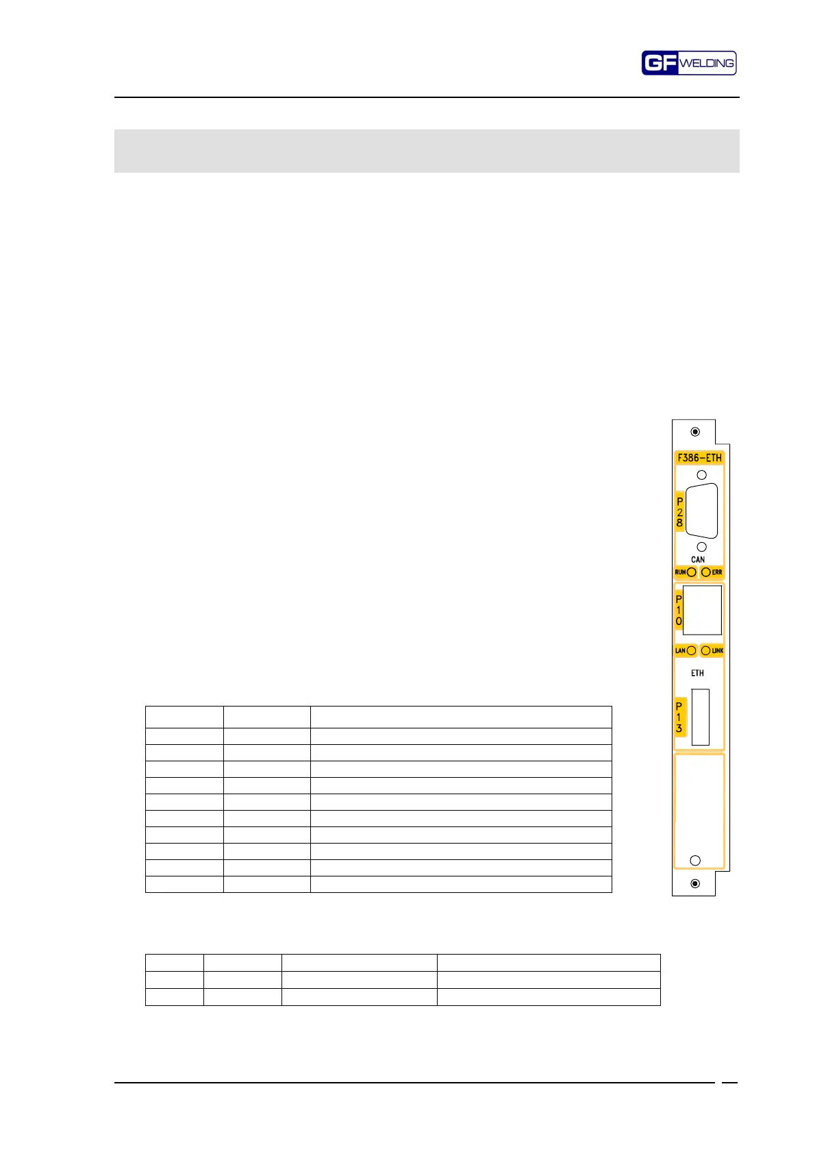
Front panel
12.2.1
P28 – CANbus connector
Sub-D 9-pole male type
Pin Signal Function
1- Reserve
6* GND CAN Ground
2 CAN_L CAN_L bus line (dominant low)
7 CAN_H CAN_H bus line (dominant high)
3* CAN_GND CAN Ground (optional)
8- Reserve
4- Reserve
9 CAN_V+ CAN external positive supply (optional line)
5 CAN_SHLD CAN Shield (optional)
Shield PE
Pins 3 and 6 are interconnected to each other
12.2.2
CANbus status LED’s
LED Colour Meaning Condition
RUN Green CAN peripheral status On = active
ERR Red Anomaly On = generic anomaly
: