3. Identify the prescribed location of the OrPAY1000 on the fuel pump housing. Draw a horizontal
reference line to allow correct alignment of the lower edge of the drilling template
4. Use the drilling template (place the plate with the arrow up) and mark the five holes on the pump
retrofit surface
5. Drill five 4 mm holes in accordance with the template
6. Drill the middle hole to the final diameter desired, based on communication and power cables used
7. Thoroughly clean burrs on the hole edges
8. Drill the four corner holes to the final diameter, 4 mm
9. Inspect the hole and check for correct location according to the template
10. Clean the surface intended for installing the OrPAY1000
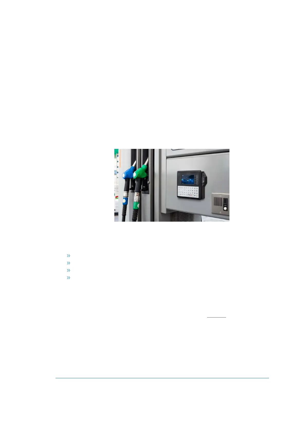
11. Insert the OrPAY1000 into the pump retrofit surface
12. Using two SEMS screws M4 x 10 mm (P/N 815226200), attach and tighten the OrPAY1000 to the
pump retrofit surface
Figure 4-6 - OrPAY1000 on Pump Retrofit
4.3. Wiring
Three connections need to be made to the OrPAY1000:
Ground
Ethernet LAN
DC Power supply -485
(Optional) Pump wires
The DC power supply cable also needs to be connected to the power supply.
4.3.1. Protective Earth
OrPAY1000 is provided with a ground tab mounted on the bottom frame (see Figure 4-7).
The tab must be connected to the pump (or cabinet) frame to provide protection from both power faults and
static discharges. The ground wire must be minimum 1.5 mm
2
and both it and the ground stud must meet
local regulations.
31 OrPAY1000 Installation and Setup Manual

 Loading...