GlobalPowerTechnologies 3-7
5120
3.2.3 Air Supply
Thescreenatthefrontoftheburnermaybecomecloggedwithdustandinsectstherebypre-
ventingtheproperowofairtotheburner.Tocleanitproceedasfollows:
1) Shut-othefuelsupplytotheTEG.
2) Disconnecttheexiblefuellinefromthefrontoftheburner.
3) Removetheoricetting,theadjustingscrewlocknutandthetwowing-nuts.
4) Removethescreen.
5) Cleanthescreenbyforcingairthroughitorwashinginwater.
6) Replacescreenandttings.
7) Turntheventuriadjustingscrewcounter-clockwiseasfarasitwillgothenturnitclock-
wisefourturns.Thiswillsettheadjustmentinthecorrectrangetobeginbalancingthe
air-fuelmixturewhenre-starting.
8) Beforere-startingtheTEG,leakcheckallfuelconnections.
3.2.4 Burner
TheBurnersystemcontainstheventuriandairlterassemblieswhichallowforadjustmentof
theair/fuelmixture.Thismixturepassesthroughtheventuritothebackoftheburnerwhere
combustiontakesplace.AproblemintheburnerissuspectedonlyifV
set
cannotbebrought
uptoratedpower.Makesurethefuelsystemandairsupplyareokaybeforeproceedingto
servicetheburner.
3.2.4.1 Removing the Burner
Allowthegeneratortocoolthenproceedasfollows:
1) Disconnectthehighvoltagewirefromthesparkelectrode.
2) Loosenthewing-nutandslidethesparkelectrodeout.
3) Removethewing-nutnearthebottomoftheexhauststackthenslidetheexhauststack
out.
4) Disconnecttheexiblefuellinefromthefrontoftheairscreen.
5) Removetheoricetting.
6) Ifnecessary,disconnectandremovethefuelsystem(SeeSection3.2.2).
7) Removethefourwing-nutsholding
the burner in place and slide the
burner out.
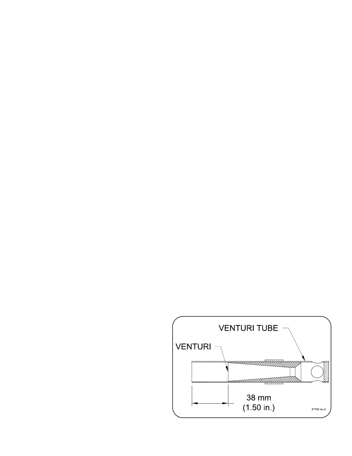
3.2.4.2 Inspecting the Burner
(Figure 18)
1) Check the venturi assembly. If it
looks severely corroded it should
bereplaced.Makesuretheventuri
is properly located in the venturi
tube (1.50” from end, Figure 17),
and that the venturi is facing the
properdirection.
Figure 17 VenturiLocation