GlobalPowerTechnologies 6-9
5120
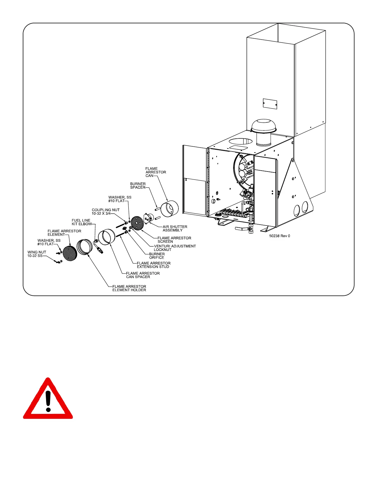
h) Rotatethefuel line elbowandflamearrestor can spacersothat the notchinthecan
alignswiththegrooveofthegrommetonthefuellineelbow.Makesurethatthefuelline
fittingpointsawayfromthecombustionchamberexhausttubes,thentightenthefuelline
fittingontothefuelorificewithtwo9/16wrenches.SeeFigure36.
i) Connectoneendoftheflexiblefuellinetothefuelmanifold.Connectandtightenthe
freeendoftheflexiblefuellinetothefittingonthefuellineelbowkitusinga9/16wrench.
WARNING: Check the system for fuel leaks at this point!
j) Rotatethe flame arrestor element holder so that the notch in the can aligns with the
grooveofthegrommetonthefuellineelbow.Slidetheflamearrestorelementholder
insidetheflamearrestorcanspacer.
Figure 36 IntakeFlameArrestorInstallation