GlobalPowerTechnologies 6-7
5120
g) Remove the air shutter and burner
spacers.Savetheseitemsforinstal-
lationwiththeflamearrestorintake.
h) Inspect the air shutter bore and
adjustment screw threads for evi-
denceofgallingorseizing.
j) Replacetheappropriatepartsifnec-
essary.
6.3.4 Inspection
WARNING: Before proceeding
any further, carefully inspect
the following important
items. Repair or replace as
necessary.
a) InspecttheS.I.electrodecarefully.If
itisdamaged,ortheceramicinsula-
tor is cracked it MUST be replaced
withGPTP/N4200-02032.
b) Visuallychecktheoricehole.Itshouldbefreefromanyobstructions.Replaceifnec-
essary.
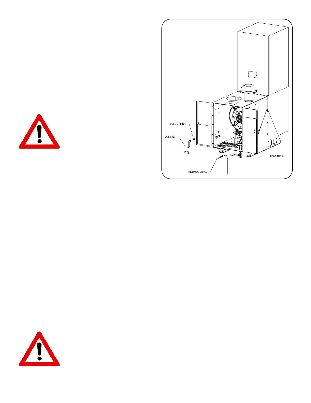
c) Inspect the thermocouple carefully. If it is damaged, or threads on the lock nut are
stripped,disconnectthethermocoupleconnectorfromthebaseoftheSOvalvewitha
3/8wrench,andreplacethethermocouplewithGPTP/N3400-00177.
d) Inspecttheairshutterboreandadjustmentscrewthreadsforevidenceofgallingorseiz-
ing.Replacetheappropriatepartsifnecessary.
e) InspecttheBurnerCoverassemblyasitisinstalledintheTEG.SeeFigure35.Ifthere
isanydeformationoftheexhausttubes,oriftheBurnerCoverplatehaswarpedand
isnolongerat,thecompleteburnerneedstobereplacedoroverhauledbyqualied
personnel.
6.4 INSTALLATION
WARNING: Follow the installation procedures carefully! The flame arrestor
design and these instructions are intended to keep all joints or seams
between parts tight. Failure to follow these instructions exactly, using worn
or damaged parts, or installing items incorrectly may result in personal inju-
ry or death and possible damage to the equipment and/or property.
Figure 34FuelLineandThermocouple
Removal