GlobalPowerTechnologies 6-4
5120
6.2.1 Trained Operators
Personnelperforminginstallation,operation,serviceandmaintenanceworkshouldbeproperly
trainedinsuchfunctions.Installationofthisamearrestorkitmustbeperformedbyaqualied
servicepersonwhomustinspectthegeneratorbeforeinstallationandagainaftertheset-upis
complete.Qualiedservicepersonnelmustalsoperformanannualinspectionofthegenerator
andamearrestor.
6.2.2 Surface Temperatures
When the TEG is operating, surface temperatures in the vicinity of the thermopile, burner,
exhauststackandaroundthecoolingnsmaybeinexcessof100°C.Avoidcontactofskin
andclothingwiththeseareaswhenoperatinginandaroundtheTEG.AllowtheTEGtocool
sucientlybeforeperforminganywork.Theburnerareacanremainveryhotforsometime
aftershutdown.
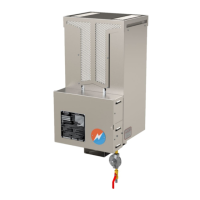
6.3 DISASSEMBLY
Before installing the Flame Arrestor kit, the existing Exhaust Stack, Inner Stack, Fuel Line,
Thermocouple and Air Intake must be removed. Figure 32 shows the items that must be
removed.Seebelowforthedisassemblyprocedure.
WARNING: Allow the TEG to cool sufficiently before performing any work. The
burner area and exhaust can remain very hot for some time after shutdown.
6.3.1 Remove Stacks:
Figure33showstheremovaloftheinnerandouterexhauststacks.
Removetheouterexhauststackassemblybylooseningthebandclampinsidethetopofthe
TEGcabinet.Leavetheintakestackassemblyinplace.
RemovetheS.I.electrode by loosening the large wingnutonthefront of the inner exhaust
stackandpullingtheelectrodestraightout.Inspecttheelectrodecarefully.Ifitisdamaged,or
theceramicinsulatoriscrackeditMUSTbereplacedwithGPTP/N4200-02032.
Removetheinnerexhauststackassemblybyremovingthesmaller10-32wingnutonthefront
oftheexhauststack,thengentlypullingtheinnerstackassemblystraightback.Savethewing
nutfortheinstallationofthenewinnerstack.
6.3.2 Remove Fuel Line and Thermocouple:
Figure34showstheremovalofthefuelline,fueloriceandthermocouple.
a) Disconnecttheflexiblefuellinefromthefuelmanifoldusinga9/16wrench.