GlobalPowerTechnologies 6-11
5120
f) Feedtheelectrodethroughtheholeinthemountingpin,thentheholeinthemounting
bracket and through the electrode hole in the burner back. Adjust the spark gap as
directedintheappropriatesectionoftheTEGoperatingmanual.
g) Tightenthewingnutonlyuntilitissnug.
Caution: Do not over tighten the wing nut or the ceramic rod will crack.
h) Connectthehighvoltagesparkwiretotheelectrode.
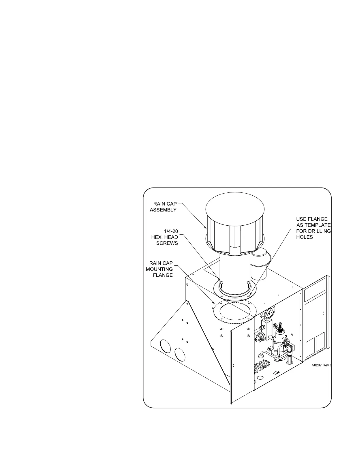
6.4.3 Install Rain Cap Assembly:
Figure38showstheinstallationoftheRainCapAssembly.
a) Usingthemountingflangeasatemplate,drill4holes(9/16diameter)inthetopofthe
cabinet.
b) Installtheraincapassemblyinthelargeholeinthecabinettop,centeredovertheflame
arrestorinnerstack.
c) Installthemountingflangefrominsidethecabinet.Usethe1/4-20Hexheadscrews,
washersandnutstofasten
inplace.
Figure 38RainCapInstallation