GlobalPowerTechnologies 3-10
5120
3) Checkthebatteryvoltageasfollows:
a) Measurethevoltagebetweenthebrownleadandterminal4ofTB-1.Thevoltage
shouldbegreaterthan2volts.
b) Ifthevoltageislessthan2voltsthebatteryneedsrechargingorreplacing.
c) Makesureallwireconnectionsaresecure.
4) Checkthebatterychargerandsparkgeneratorasfollows:
a) ManuallylighttheTEGbyplacingalightedmatchattheportoftheSIelectrode.
b) Aftertwentyminutesofoperationcheckthebatteryvoltageasperstep3.The
voltageshouldbe2.35volts.
c) Performstep1again.Ifsparkingdoesnotoccurthecontrolmoduleneedstobe
replaced.
5) Checkifthebatterywillholdchargeasfollows:
a) Removethethinwhite/redwirefromterminal2ofTB-1.
b) Connecttheorangewiretothebrownwire.
c) Measurebatteryvoltagebetweentheorangewireandterminal4ofTB-1.
d) Ifthevoltageislessthan2.0volts,replacethebattery.
e) Toreplacethebatteryopenthecontrolmodule.
f) Disconnectthebatteryleads.
g) Installanewbattery,takingnoteofpolarity.
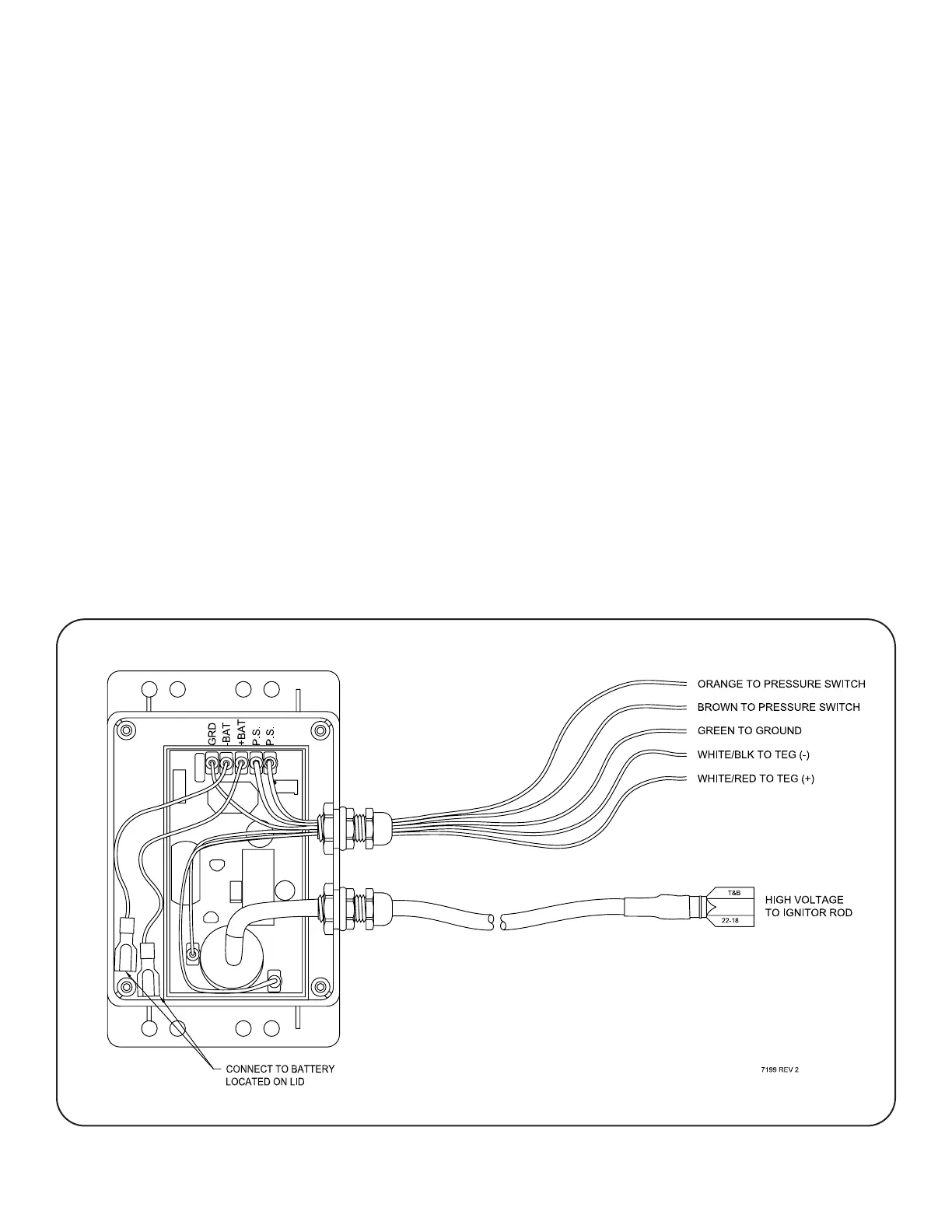
Figure 19 SparkIgnitorWiringDiagram