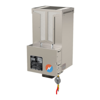
GlobalPowerTechnologies 6-8
5120
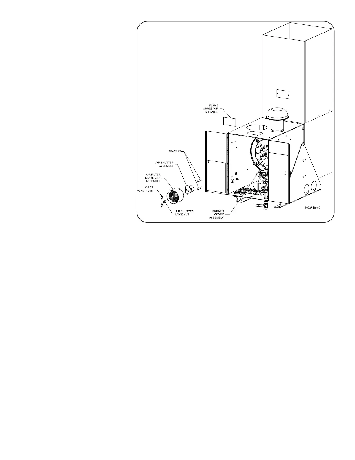
6.4.1 Install Flame Arrestor Air
Intake:
Figure 36 shows the instal-
lation of the Flame
ArrestorAirIntake.
a) Install the Flame
ArrestorCanoverthe
Venturitubeassembly
and the two stud bolts
protruding from the
combustion chamber
assembly.Makesure
that the base of the
can sits tight to the
combustion chamber
backplate.
b) Install the burn-
er spacers over the
combustion chamber
stud bolts and slide
theairshutterassem-
bly over the bolts, up
tothespacers.
c) Carefullyplacetheflamearrestorscreenoverthecombustionchamberstudbolts,ven-
turiadjustmentscrewandinsidetheflamearrestorcan.Installtwo(2)#10flatwash-
erstoprotectthescreen,theninstallthetwo#10-32x¾couplingnutsandtheventuri
adjustmentlocknut.
d) Close the air shutter completely by turning the air shutter adjustment screw counter
clockwise.Thensettheairshutterbyturningtheadjustmentscrewclockwisethree(3)
tofour(4)fullturnsclockwise.
e) Installtheburnerorificethroughtheflamearrestorscreenandtightenonlyhandtightinto
theventuritubeassemblyinlet.
Caution: Always use the correct size burner orice, 5120 Natural Gas Orice (#8),
GPTP/N4200-00690. Theamearrestorkitisnotapprovedforuseona
5120 generator operating on propane fuel.
f) Installthetwo(2) flame arrestorextensionstudsinto thecouplingnutsand place the
flamearrestorcanspaceroverthestuds.
g) Install,butdonottightenyet,thefuellinekitelbowintothefuelorificefitting.Notethat
theshortlegoftheelbow,withoutthegrommet,attachestotheorifice.
Figure 35AirIntakeandAirShutterRemoval