GlobalPowerTechnologies 4-2
5120
4.2 Operation
4.2.1 Preparation for Use
Thepowerconditionerisshippedreadyforoperation.Ifthelimiterconverterwasshippedsep-
arately,itshouldbeinspectedforobviousdentsorbrokencomponents.Notifythecarrierifso.
4.2.2 Installation
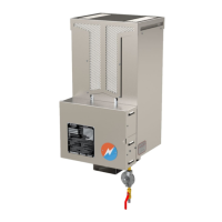
Thestandardmountinglocationison therightside
ofthegeneratorcabinet.Removethenutsandlock
washers and mount to the outside of the cabinet.
Feedthewiresintothecabinetthroughtheholepro-
vided. Refer to Figure 26 to identify the input and
outputwires.
Check the selector switch setting (Figure 26)
BEFOREconnectingtheinputoroutputwirestothe
terminalblock.
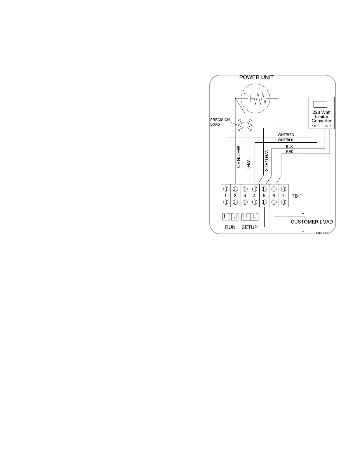
Connect the 220 Watt L/C to the terminal block as
perFigure25.
Remotemountingofthelimiterconverterisaccept-
able,but allowfor17Ampsbetweenthegenerator
andthelimiterconverterwhensizingwire.
Thelimiter convertermustalways bemountedin an
uprightpositiontoallowairtopassfreelyovertheheatsinksection.
4.2.3 Output Voltage Adjustment
The220Wattlimiterconverterisfactorysetat14.1Voltsor27.0Voltsdependingontheoutput
ordered.TotrimtheoutputvoltageusetheoutputvoltageadjustmentpotshowninFigure26.
TochangetheoutputvoltagerangeusetheselectorswitchinFigure26.
4.2.4 Protective Limiter
Aprotectivelimitercircuitisincorporatedintothe220WattL/Ctolimittheinputvoltage.This
settingcanbemeasuredacrosstheTEGPOSandTEGNEGterminalswithnoloadconnect-
ed.The220WattL/Cisfactorysetat10Voltsfora5120,16Voltsfora5220and9Voltsfor
a5060.Whenusinga220WattL/Conageneratorotherthanwhatitwasfactorysetfor,the
protectivelimitermustbereadjustedatthefactory.
4.2.5 Voltage Sensing Relay Adjustment
TheVSRisfactorysetat11.5Voltsfor14.1Voltoutputandat23.0Voltsfora27.0Voltoutput.
Shouldthisrequireadjustment,usetheVSRadjustmentpotinFigure26.
Figure 255120WiringDiagram