GlobalPowerTechnologies 6-10
5120
k) Rotate the flame arrestor
element so that the two
holes align with the flame
arrestor extension studs.
Install two (2), #10 flat
washers and 10-32 wing
nuts,thentighten.
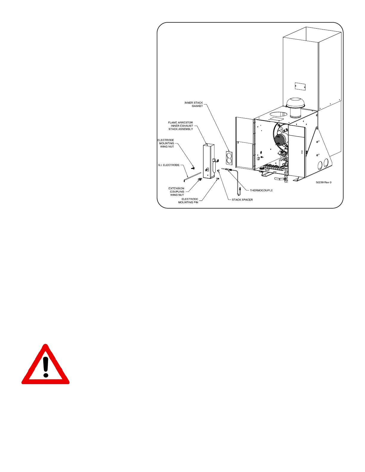
6.4.2 Install Flame Arrestor Stack
and Thermocouple:
Figure 37 shows the installation
oftheFlameArrestorinnerstack
andthermocouple.
a) Carefully place the high
temperature gasket over
the combustion chamber
exhaust tubes. The gas-
ketisCRITICALforproper
operation.Donotuseitif
it is damaged. Obtain
a new gasket, GPT P/N
3400-50198ifrequired.
b) Install the stack spacer sleeve over the 10-32 stud protruding from the burner cover
plate,directlybelowtheexhausttubes.ThespacerisCRITICALforproperoperation.
Obtainanewspacer,GPTP/N4900-50196ifrequired.
c) Carefullyinstalltheflamearrestorinnerstackassemblyovertheburnercoverexhaust
tubes and the 10-32 stud protruding from the burner cover plate, until it contacts the
hightemperaturegasket.Installthecouplingextensionwingnut(4500-50225)onthe
combustionchamberstudandtighten.Checkthatthegasketiscompressedevenly.
d) Install the thermocouple into the mounting boss on the right side of the inner stack
assembly. First, tighten the thermocouple lock nut finger tight only. Then, support
themountingbosswitha5/8wrenchandsnugthethermocouplelocknutwitha7/16
wrench.
WARNING: Do not twist the inner stack assembly when installing the thermocou-
ple, or the gasket may be damaged.
e) Looselyinstalltheelectrodemountingpinandlargewingnutintotheelectrodebracket
onthefrontoftheinnerstackassembly.
Figure 37 FlameArrestorStackandThermocouple
Installation