GMC-I Messtechnik GmbH 81
2
Known as equivalent leakage current or equivalent patient leakage current from
previous standards
3
Protective conductor current, touch current, device leakage current, patient leak-
age current
4
Protective conductor current, touch current, device leakage current
5
Only with feature G01, e.g. SECUTEST BASE10/SECUTEST PRO and SECULIFE ST BASE
6
Only with feature I01, e.g. SECUTEST PRO and SECULIFE ST BASE
7
Measurement types IPE_clamp and IG_clamp
8
Measurement type IPE_AT3 adapter and IG_AT3 adapter
9
The upper range limit depends on the selected test voltage.
10
Voltage at the test socket may be lower than measured line voltage due to com-
ponents which limit inrush current.
11
Only with feature G02, e.g. SECULIFE ST BASE25
Key: rdg. = reading (measured value), d = digit(s)
Testing Times, Automated Sequence
Testing times (“measurement duration” parameter) can be set separately
for each rotary switch position during configuration of the sequence
parameters. Testing times are neither tested nor calibrated.
Emergency Shutdown During Leakage Current Measurement
As of 10 mA of differential current (can also be set to 30 mA),
automatic shutdown ensues within 500 ms. This shutdown does
not take place during leakage current measurement with clamp
meter or adapter.
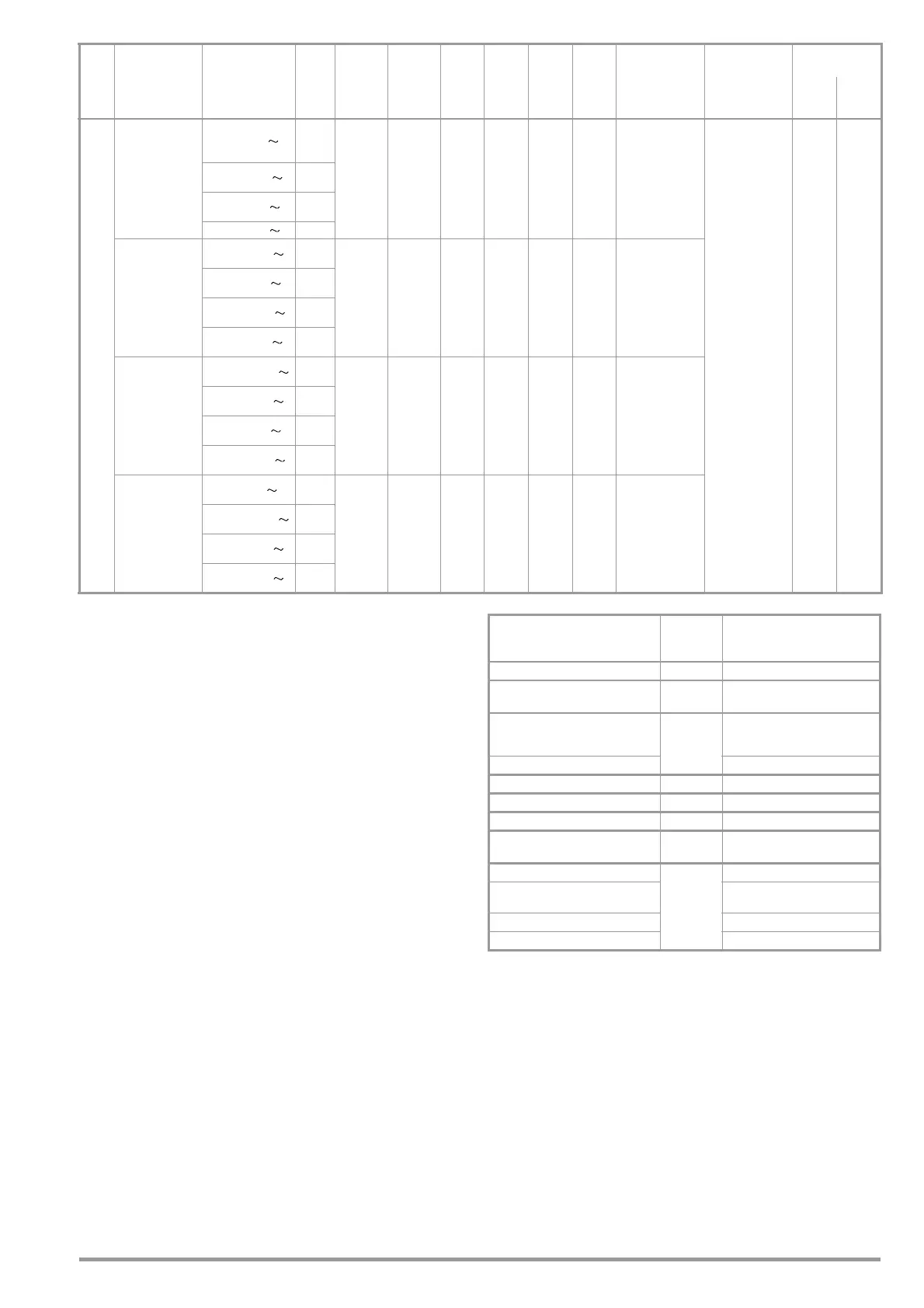
Influencing Quantities and Influence Error
I
Clamp
Current via
current clamp
sensor
[1 mV : 1 mA]
(V–COM
sockets
6, 7
)
1 ... 99 mA
1mA
(1 mV)
— — ———— —
±(2 % rdg.+2 d)
>10d
20 Hz ... 20 kHz
without clamp
253 V
Continu-
ous
0.1 ... 0.99 A
0.01 A
(10 mV)
1.0 ... 9.9 A
0.1 A
(100 mV)
10 ... 300 A
1A
(1 V)
Current via
current clamp
sensor
[10mV : 1mA]
(V–COM
sockets
6, 7
)
0.1 ... 9.9 mA
0.1 mA
(1 mV)
— — ———— —
10 ... 99 mA
1mA
(10 mV)
0.10 ... 0.99 A
0.01 A
(100 mV)
1.0 ... 30.0 A
0.1 A
(1 V)
Current via
current clamp
sensor
[100 mV : 1 mA]
(V–COM
sockets
6, 7
)
0.01 ... 0.99 mA
0.01 mA
(1 mV)
— — ———— —
1.0 ... 9.9 mA
0.1 mA
(10 mV)
10 ... 99 mA
1mA
(100 mV)
0.10 ... 3.00 A
0.01 A
(1 V)
Current via
current clamp
sensor
[1000 mV : 1 mA]
(V–COM
sockets
6, 7
)
1 ... 99 μA
1μA
(1 mV)
— — ———— —
0.10 ... 0.99 mA
0.01 mA
(10 mV)
1.0 ... 9.9 mA
0.1 mA
(100 mV)
10 ... 300 mA
1mA
(1 V)
Func-
tion
Measured
Quantity
Display Range/
Nominal Range of
Use
Reso-
lution
Nominal
Voltage
U
N
Open-
Circuit
Voltage
U
0
Nomi-
nal
Current
I
N
Short-
Circuit
Current
I
K
Internal
Resis-
tance
R
I
Refer-
ence
Resis-
tance
R
REF
Measuring
Uncertainty
Intrinsic
Uncertainty
Overload
Capacity
Value Time
Influencing Quantity /
Sphere of Influence
Designation
per
IEC 61557-16
Influence Error
± … % rdg.
Change of position E1 —
Change to test equipment supply
voltage
E2 2.5
Temperature fluctuation
E3
Specified influence error valid
starting with temperature changes
as of 10 K:
0 ... 40
°C2.5
Amount of current at DUT E4 2.5
Low frequency magnetic fields E5 2.5
DUT impedance E6 2.5
Capacitance during insulation mea-
surement
E7 2.5
Waveform of measured current
E8
49 … 51 Hz
2 with capacitive load
(for equivalent leakage current)
45 … 100 Hz 1 (for touch current)
2.5 for all other measuring ranges

 Loading...


