AC
AA
AF
AE
AD
AB
AM
AL
AK
AJ
AN
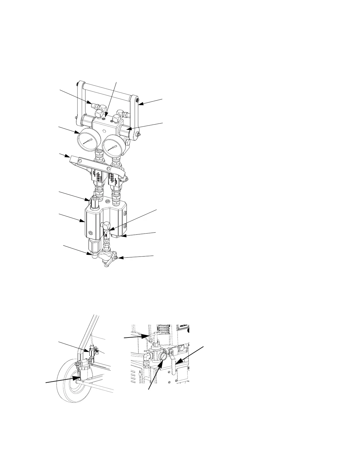
Key:
AA Fluid Manifold
AB Mix Manifold
AC Circulation Handle
AD Solvent Flush Valve
AE Dual Shutoff Handle
AF Fluid Pressure Gauges
AG Fluid Supply Inlet (Behind Fluid Manifold)
AH Fluid Circulation Fittings
AJ B Component Adjustable Fluid Restrictor; see
page 29
AK A and B Mix Manifold Check Valves
AL Solvent Inlet Check Valve
AM Automatic, Spring Loaded, Color-Coded Over
Pressure Relief Valves; with grease fittings; see
page 42
AN A and B Combined Outlet; 3/8 npt(m)
AH
ti19167a
Standard Mix Manifold shown
CA
CD
CB
CC
Key:
CA Main Motor Shutoff Valve (Relieving)
CB Main Motor Air Pressure Regulator
CC Air Filter with Auto Drain
CD Main Motor Air Pressure Gauge
CE Filtered Air Distribution Manifold
CE