2 3A0420V
Contents
Related Manuals . . . . . . . . . . . . . . . . . . . . . . . . . . . 3
Warnings . . . . . . . . . . . . . . . . . . . . . . . . . . . . . . . . . 4
Important Two-Component Material Information . 7
Isocyanate Conditions . . . . . . . . . . . . . . . . . . . . . 7
Material Self-ignition . . . . . . . . . . . . . . . . . . . . . . 7
Keep Components A and B Separate . . . . . . . . . 7
Moisture Sensitivity of Isocyanates . . . . . . . . . . . 7
Foam Resins with 245 fa Blowing Agents . . . . . . 7
Changing Materials . . . . . . . . . . . . . . . . . . . . . . . 8
A and B Component Designations . . . . . . . . . . . 8
Overview . . . . . . . . . . . . . . . . . . . . . . . . . . . . . . . . . . 9
Usage . . . . . . . . . . . . . . . . . . . . . . . . . . . . . . . . . 9
Over Pressure Protection . . . . . . . . . . . . . . . . . . 9
Initial System Setup . . . . . . . . . . . . . . . . . . . . . . . 10
Models . . . . . . . . . . . . . . . . . . . . . . . . . . . . . . . . . . 11
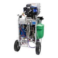
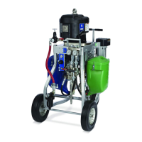
Cart-Mounted Systems . . . . . . . . . . . . . . . . . . . 11
Bare Proportioning Pump Packages . . . . . . . . . 14
Component Identification . . . . . . . . . . . . . . . . . . . 15
XP Proportioners . . . . . . . . . . . . . . . . . . . . . . . . 15
XP-h Proportioners . . . . . . . . . . . . . . . . . . . . . . 16
Fluid Control Assembly . . . . . . . . . . . . . . . . . . . 17
Main Air Controls . . . . . . . . . . . . . . . . . . . . . . . 17
45:1 Solvent Flush Pump Kit 262393 (optional) 18
Air Line . . . . . . . . . . . . . . . . . . . . . . . . . . . . . . . 19
Fluid Line Accessories . . . . . . . . . . . . . . . . . . . 19
Flush Before Using Equipment . . . . . . . . . . . . . 19
Setup . . . . . . . . . . . . . . . . . . . . . . . . . . . . . . . . . . . . 20
Location . . . . . . . . . . . . . . . . . . . . . . . . . . . . . . 20
Grounding . . . . . . . . . . . . . . . . . . . . . . . . . . . . . 20
Wire Systems with Explosion-Proof Heaters . . . 21
Motor Position . . . . . . . . . . . . . . . . . . . . . . . . . . 22
Connect Air Supply . . . . . . . . . . . . . . . . . . . . . . 23
Connect Hydraulic Supply/Return Lines . . . . . . 23
Connect Static Mixers, Gun, and Hoses . . . . . . 23
Connect Fluid Hose Bundles (Remote Mix Manifold
Only) . . . . . . . . . . . . . . . . . . . . . . . . . . . . . . 23
Pressure Relief Procedure . . . . . . . . . . . . . . . . . . 24
Prime Empty System . . . . . . . . . . . . . . . . . . . . . . . 25
Prime A and B Fluids . . . . . . . . . . . . . . . . . . . . 25
Prime Solvent Flush Pump . . . . . . . . . . . . . . . . 26
Recirculate Prior to Spraying or Re-Prime After a
Pump Runs Dry . . . . . . . . . . . . . . . . . . . . . 27
Spray . . . . . . . . . . . . . . . . . . . . . . . . . . . . . . . . . . . . 28
B Side Mix Manifold Restriction . . . . . . . . . . . . . . 29
Flush Mixed Material . . . . . . . . . . . . . . . . . . . . . . . 30
Flush Mix Manifold, Hose, and Spray Gun . . . . 30
Empty and Flush Entire System
(new system or end of job) . . . . . . . . . . . . . . . 31
Shutdown . . . . . . . . . . . . . . . . . . . . . . . . . . . . . . . . 33
Park . . . . . . . . . . . . . . . . . . . . . . . . . . . . . . . . . . . . . 33
System Verification . . . . . . . . . . . . . . . . . . . . . . . . 34
Maintenance . . . . . . . . . . . . . . . . . . . . . . . . . . . . . . 35
Hose Electrical Resistance . . . . . . . . . . . . . . . . 35
Filters . . . . . . . . . . . . . . . . . . . . . . . . . . . . . . . . . 35
Seals . . . . . . . . . . . . . . . . . . . . . . . . . . . . . . . . . 35
Cleaning Procedure . . . . . . . . . . . . . . . . . . . . . . 35
Recommended Spare Parts . . . . . . . . . . . . . . . 35
Change the Mix Ratio . . . . . . . . . . . . . . . . . . . . 35
Troubleshooting . . . . . . . . . . . . . . . . . . . . . . . . . . . 36
Pump Troubleshooting . . . . . . . . . . . . . . . . . . . 37
Repair . . . . . . . . . . . . . . . . . . . . . . . . . . . . . . . . . . . 38
Pump Assembly . . . . . . . . . . . . . . . . . . . . . . . . . 38
Air Controls . . . . . . . . . . . . . . . . . . . . . . . . . . . . 39
Mix Manifold Assembly . . . . . . . . . . . . . . . . . . . 41
Fluid Circulation Manifold with Over Pressure Relief
Valves . . . . . . . . . . . . . . . . . . . . . . . . . . . . . 41
Hoppers . . . . . . . . . . . . . . . . . . . . . . . . . . . . . . . 43
Optional Solvent Pump . . . . . . . . . . . . . . . . . . . 43
Optional Fluid Heaters . . . . . . . . . . . . . . . . . . . . 44
Parts . . . . . . . . . . . . . . . . . . . . . . . . . . . . . . . . . . . . 46
Cart-Mounted System . . . . . . . . . . . . . . . . . . . . 46
Bare Proportioning Pump Package . . . . . . . . . . 56
Air Controls, 258983 . . . . . . . . . . . . . . . . . . . . . 58
Fluid Circulation Manifold with Over Pressure Relief
Valve . . . . . . . . . . . . . . . . . . . . . . . . . . . . . . 59
Recommended Spare Parts . . . . . . . . . . . . . . . . . 60
Accessories and Kits . . . . . . . . . . . . . . . . . . . . . . . 61
Acceptable For Use in Explosive Atmospheres . 61
Not Approved For Explosive Atmospheres . . . . 62
Technical Data . . . . . . . . . . . . . . . . . . . . . . . . . . . . 63
Dimensions . . . . . . . . . . . . . . . . . . . . . . . . . . . . . . 64
Bare Proportioner Mounting Hole Dimensions . 66
Wall Mount Bracket 262812 Dimensions . . . . . . 67
Floor Stand 24M281 Dimensions . . . . . . . . . . . 68
Hydraulic Unit Dimensions . . . . . . . . . . . . . . . . 68
Graco Standard Warranty . . . . . . . . . . . . . . . . . . . 70