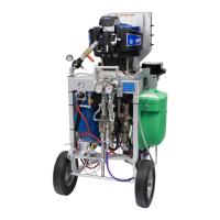
Component Identification
16 3A0420ZAF
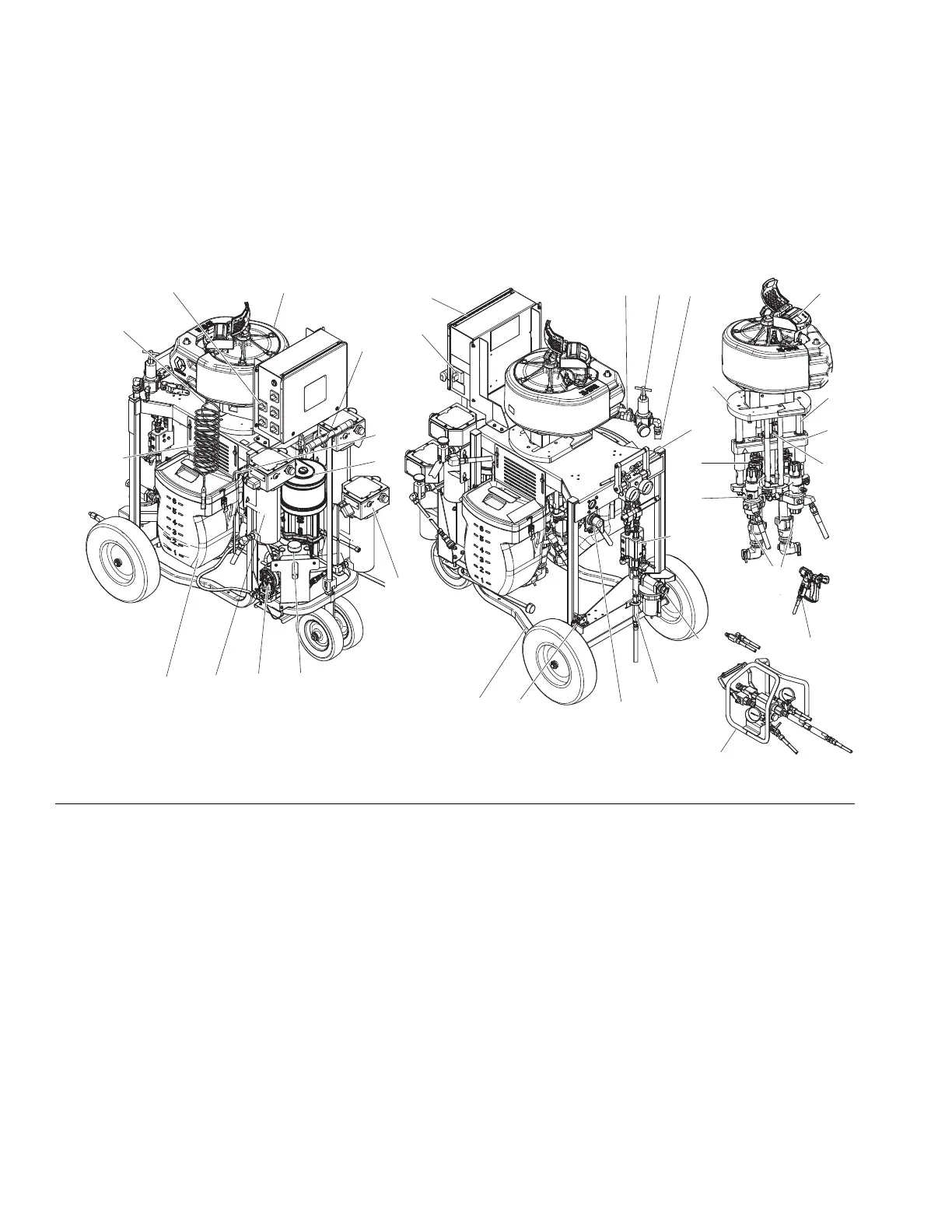
Component Identification
XP Proportioners
Key:
A Air Supply Hose for Motor
B Main Air Controls; see page 18
C Air Inlet - 3/4 npsm(f)
D High Pressure Fluid Pump
E Air Motor
F Fluid Heater
G Solvent Flush Pump; see page 19
H Solvent Flush Pump Air Controls; see page 19
J 7 Gallon Hoppers
KCart
LBrake
M Handle (lift to release)
N Fluid Control Assembly; see page 18
P Tie Rods
R Motor Adapter Plate
S Adjustable Packing Nuts with Wet Cups
T Yoke With Rod Bearings
U Recirculation Lines
V Yoke Position Nut
W Static Mixer Tubes with Replacement Plastic Elements
X Motor Position Indicator Lines; see Motor Position on
page 25
Y Over Pressure Rupture Disc;
Z Air Motor Ground Wire
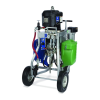
AA PressureTrak
AB Junction Box
AC Circulation Pump Reservoir
AD Circulation Pump
AE Viscon HP Hose Water Heater
AF Heater ON/OFF Switches
AG Power Disconnect Switch
MA Main Shutoff Valve
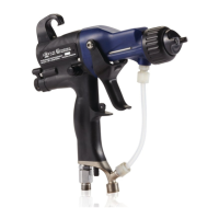
GN Gun
RM Remote Manifold
FIG. 1: XP70 Complete System (model 576107 shown)
WLE
$*
0
%
$
&
''
)
*
+
-
.
/
1
3
5
6
7
8
8
9
:
;
<
$$
$%
$&
$'
$(
$)
=
0$
50
(
*1