Setup
22 3A0420ZAF
Setup
Location
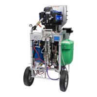
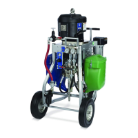
1. Locate the proportioner on a level surface.
2. Position the proportioner for convenient operator
access and maintenance, proper routing of air and
fluid lines, and easy connection of components and
accessories.
3. For permanent mounting, remove wheels and
mount the frame to the floor. See Dimensions,
page 85.
4. Make sure cart brake (L) is in the locked position.
Initial System Setup
1. Check the shipment for accuracy. Ensure you have
received everything you ordered. See Component
Identification, page 16.
2. Check for loose fittings and fasteners.
3. If any accessories are added, refer to Related
Manuals, page 3.
4. Install desiccant kits if using polyurethane
isocyanates in hoppers. See your desiccant kits
manual for instructions.
5. Install circulation and return tube kits if you are
feeding material from drums or remote hoppers.
See your circulation and return tube kits manual if
you are feeding urethane material.
6. Connect the feed pumps, fluid strainers, and air
hoses as necessary. For systems without hoppers,
see your feed pump and agitator kits manual.
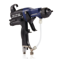
7. Connect the fluid hose assembly, including the
static mixers, whip hose and gun. See Connect
Static Mixers, Gun, and Hoses, page 27.
8. Connect the battery in the PressureTrak module.
See your XP Pressure Monitor manual.
9. XP Units: Connect the air supply hose. See
Connect Air Supply, page 27.
XP-h Units: Connect the hydraulic lines. See your
GH power pack manual for instructions.
Flush test oil from system as needed. See Pressure
Relief Procedure, page 30. See Empty and Flush
Entire System (new system or end of job), page
39.
Flush Before Using Equipment
The bare pump package was tested with lightweight oil,
which is left in the fluid passages to protect parts. To
avoid contaminating your fluid with oil, flush the
equipment with a compatible solvent before using the
equipment. See Empty and Flush Entire System (new
system or end of job), page 39.
Using an XP system, or components on the system, not
approved for hazardous locations or explosive
atmospheres may result in a fire or explosion hazard.
The XP systems are not approved for use in hazardous
locations unless the base model, all accessories, all
kits, and all wiring meet local, state, and national codes.
See Systems with Explosion-Proof Heaters on page
25.