Overview
3A0420ZAF 9
Overview
Usage
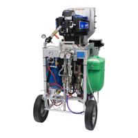
The XP and XP-h systems are mechanically linked fixed
ratio systems that can mix and spray most
two-component epoxy and urethane protective coatings.
XP systems include: Cart frame, XP pump assembly,
XTR and 35 ft (10.7 m) of supply hose, various options
are specified by the last digit (see page 12 for details).
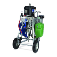
XP-h systems include: Cart frame, XP-h pump
assembly, XTR and 35 ft (10.7 m) of supply hose (see
pages 13-14 for various other options). The Power Pack
used to power the XP-h motor is sold separately. See
your GH Power Pack manual for details.
When using quick-setting material (less than 10 minute
pot life), the Remote Manifold Heater Block Kit (24Z934)
is recommended for use (see page 12 for models).
The two high pressure fluid pumps are carbide or
stainless steel seat severe duty positive displacement
pumps that displace fluid on both strokes.
Over Pressure Protection
Using an XP system, or components on the system,
not approved for hazardous locations or explosive
atmospheres may result in a fire or explosion hazard.
The XP systems are not approved for use in
hazardous locations unless the base model, all
accessories, all kits, and all wiring meet local, state,
and national codes.
See Systems with Explosion-Proof Heaters on page
25.
Mechanically linked pumps can create excessive fluid
pressure if the full motor force is applied to only one of
the fluid pumps.
• XP Systems Only: Maximum air pressure set point
blow off valves are provided to limit maximum fluid
pressure. Do not remove these valves.
• Color coded automatic over pressure relief valves
are used on cart-mounted systems to dump excess
fluid pressure back to the supply. Never plug these
return hoses. See Fluid Circulation Manifold with
Over Pressure Relief Valves on page 51.
• When using an XP bare pump package to build a
system, use the over pressure relief valves
referenced above.
• Never install individual shut off valves on the “A” and
“B” lines. On cart-mounted systems, common
handles link the fluid control valves.
• A rupture disc is provided on the small side fluid
pump (pumps 145 cc and smaller) as a back-up to
the over pressure relief valve. If the rupture disc ever
opens, do not operate the machine until the over
pressure valve and the rupture disc have been
replaced.
• If changing pump lowers or motor on your system,
use the correct over pressure relief valves from the
chart on page 52.