For XP systems only.
FC
FA
FF
FE
FD
FB
FM
FL
FK
FJ
FN
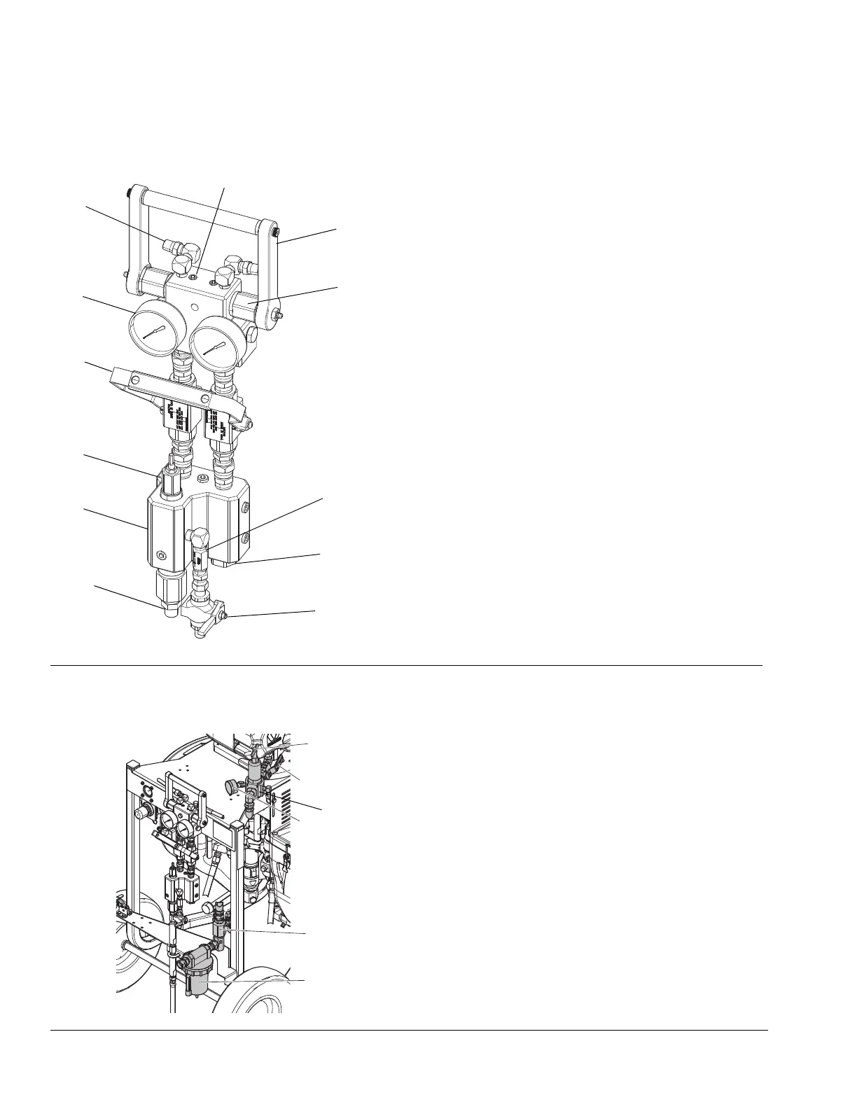
Key:
FA Fluid Manifold
FB Mix Manifold
FC Circulation Handle (shown closed)
FD Solvent Flush Valve
FE Dual Shutoff Handle (shown closed)
FF Fluid Pressure Gauges
FG Fluid Supply Inlet (Behind Fluid Manifold)
FH Fluid Circulation Fittings
FJ B Component Adjustable Fluid Restrictor; see page 36
FK A and B Mix Manifold Check Valves
FL Solvent Inlet Check Valve
FM Automatic, Spring Loaded, Color-Coded Over Pressure
Relief Valves; with grease fittings; see page 52
FN A and B Combined Outlet; 3/8 npt(m)
FH
ti19167a
Standard Mix Manifold shown
Key:
MA Main Motor Shutoff Valve (Relieving)
MB Main Motor Air Pressure Regulator
MC Air Filter with Auto Drain
MD Main Motor Air Pressure Gauge
ME Filtered Air Distribution Manifold
MG Air Pressure Relief Valve
MG