Setup
24 3A0420ZAF
Connect Power
NOTE: Systems with a junction box have heaters
pre-wired. Systems without a junction box need to
power heaters individually (refer to your Viscon HP
heater manual). If applicable, see Systems with
Explosion-Proof Heaters on page 25.
1. Turn the main power disconnect switch (AG) OFF.
2. Open the electrical enclosure door.
3. Route the power cord through the strain relief into
the electrical enclosure.
4. Connect the ground wire to ground terminal (GT).
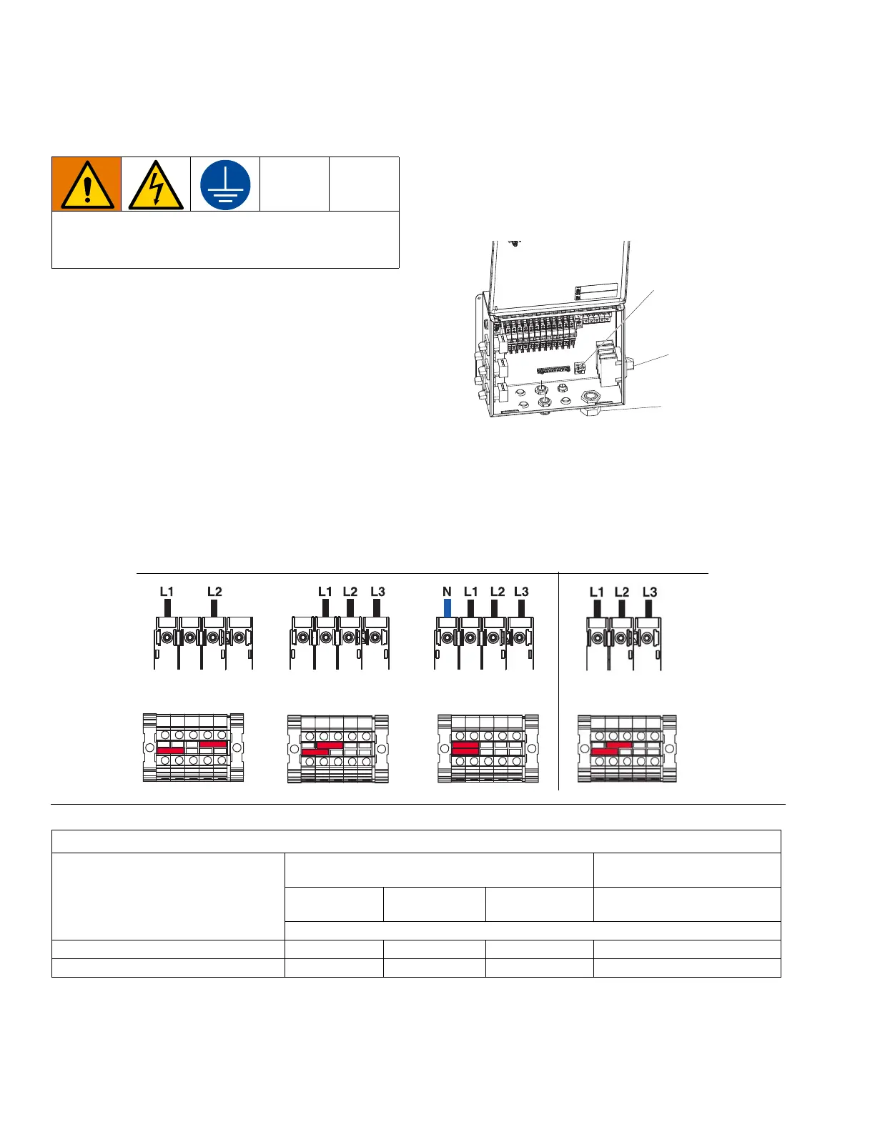
5. Connect the power cord as shown (see F
IG. 7,
Terminal Jumpers and Positions). Gently pull on
all connections to verify that they are properly
secured.
6. Tighten strain relief (SR).
7. Install the supplied terminal jumpers in the positions
shown in the image below for the power source
used.
NOTE: Terminal jumpers are located inside the
electrical enclosure door.
8. Verify that all items are connected properly as
shown below, then close the electrical enclosure
door.
NOTE: See the Junction Box XP Installation and
Parts manual for detailed instructions.
NOTE: 350-415 VAC are not designed to operate from 480 VAC power source.
All electrical wiring must be done by a qualified
electrician and comply with all local codes and
regulations.
FIG. 7 Terminal Jumpers and Positions
200-240 VAC
1-Phase
200-240 VAC
3-Phase, Delta
350-415 VAC
3-Phase, WYE
480 VAC
3-Phase, Delta
Power Requirements
XP Configuration
For use with 240 V Heaters
and/or Junction Box 273096
For use with 480V Heaters
and Junction Box 273101
200-240 VAC
1-Phase
200-240 VAC
3-Phase, Delta
350-415 VAC
3 Phase, WYE
480 VAC
3 Phase, Delta
Maximum Amperage
A & B Heaters 34 30 18 15
A & B Heaters and Heated Hose 51 45 34 22