Slicer/Applicator
SS-10.DOC:1/26/2007 11:08 AM
Grote Company
19
The following steps detail the procedure for changing to the extended position.
1. Remove the product holders.
2. Remove the bolt in the hole in front of the adjustment block. Loosen the hex head cap
screws and the adjustment jack screws.
3. Remove the pivot bolt and pull the insert (pivot shaft, roller bearing and inner-race
spacer) out of the pivot hole from the outside.
4. Move the pivot block to the extended position and reinstall the insert. Tighten the
pivot bolt into the insert.
5. Tighten the adjustment jack screw and the hex head cap screw. Place the remaining
bolt in the exposed hole on the top of the frame.
6. Adjust the height of the product holder box, the stroke length, and the stroke starting
point.
7. On multiple split-head machines, the lock pin assembly for heads 2, 4, and 6 must be
moved to the extended position whenever the product holder box is moved to the
extended position. Also adjust the roller arm of the limit switch mounted on the lock
pin assembly so that it is tripped near the end of the slicing stroke.
Slice Stroke Adjustment
Check the adjustments of the stroke length and stroke starting point by running at a very slow speed.
The motion of the product holder should be slow enough to allow the relative positions of the blade
and the product holder to be seen. Readjust as necessary until the stroke is centered over the blade
with the proper stroke length
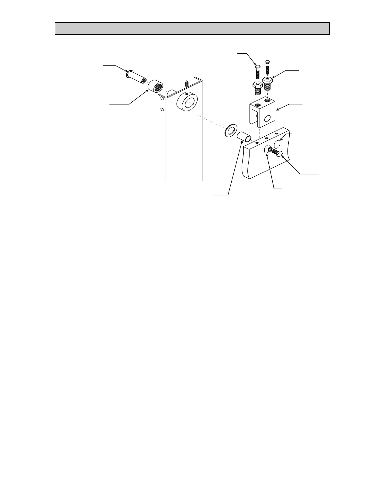
Figure 13. Product Holder Box Pivot Point - Hydraulic Machines
Pivot shaft
Roller bearing
Inner race spacer
Hex head cap screw
Adjustment jack
screw
Adjustment
block
Regular position
Extended
position
Pivot bolt
 Loading...