Slicer/Applicator
SS-10.DOC:1/26/2007 11:08 AM
Grote Company
24
8. Move to the opposite end of the blade guide and repeat steps 3 through 7 for that end of
the blade guide.
9. Return to the drive side and recheck the alignment.
10. Tighten the blade guide ball plunger until it bottoms out and back it off 1/8 turn.
Repeat this procedure on both ends of the blade guide.
Pusher Bar Adjustment
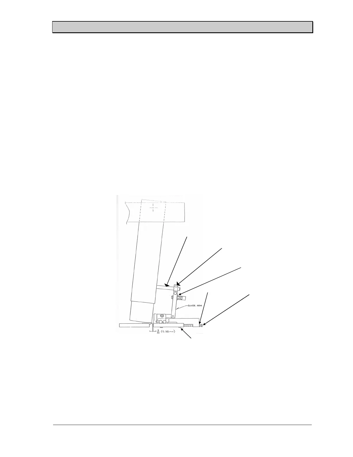
Adjust the optional product pusher bar to give approximately 3/32" (2.38 mm) clearance between
the bar and the band blade tip.
1. Loosen the four mounting bolts located on the bottom of the thickness tray. These four
bolts hold the roller guide in position.
2. Loosen the jam nuts on the adjustment bolts.
3. Turn the adjustment bolts until the proper clearance is attained. Make sure the product
pusher is parallel to the blade and tighten the jam nuts.
4. Tighten the four mounting bolts.
After the product pusher bar clearance has been set, adjust the bar so that it lightly touches the back
of the product holder when the holders are in the rest position. The following procedure details this
adjustment. Figure 19 shows the product pusher assembly.
1. Loosen the two mounting bolts that hold the product pusher assembly to the standoff.
Figure 17. Product Pusher - Hydraulic Machines
Standoff
Mounting bolt
Jam nut
Adjustment bolt
Compression spring
Mounting bolts