Chapter 4: Operation
5. When grain flow stops from the center well, close the center well gate and remove the 5/16" x 1-1/2"
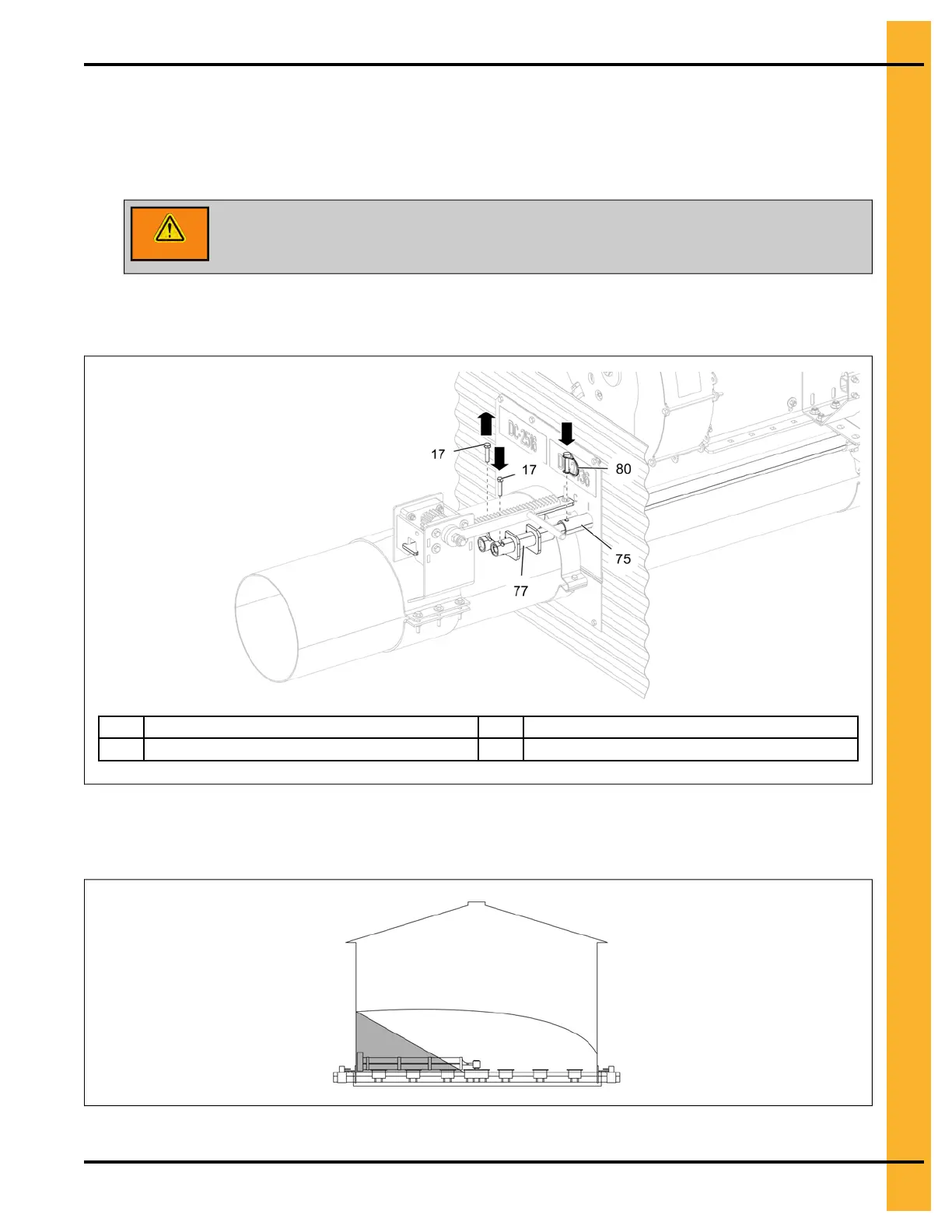
HHCS bolt (17), coupling the rack and pinion (77) tube with the center well control rod.
6. Insert the 5/16" x 1-3/8" safety pin (80) through the intermediate well control rod (75) (indicated with
“I”) and auxiliary well control rod. Also, make sure the 5/16" x 1-1/2" HHCS bolt (17) is inserted
through the rack and pinion (77) tube and auxiliary well control rod.
WARNING
When pinned correctly, all intermediate well gates will open together. Do not
open the intermediate well gates completely, as this will cause the unload to
plug.
Figure 4-6 Intermediate well control rod
17
5/16" x 1-1/2" HHCS bolt
77
Rack and pinion assembly
75 Intermediate well control rod 80 5/16" x 1-3/8" safety pin
7. Gradually open the gates until the desired flow of grain is reached. Do not open the gate more than
2" to 4". The remaining grain flow should look like as shown below.
Figure 4-7 Grain flow from the intermediate gates
Unload until grain stops flowing from the intermediate wells. At this point, close all the wells.
PNEG-2308 Chain Loop Power Sweep
61