Chapter 4: Operation
NOTE: Always close the well gates and allow the unload tube to clean out before stopping the
unload.
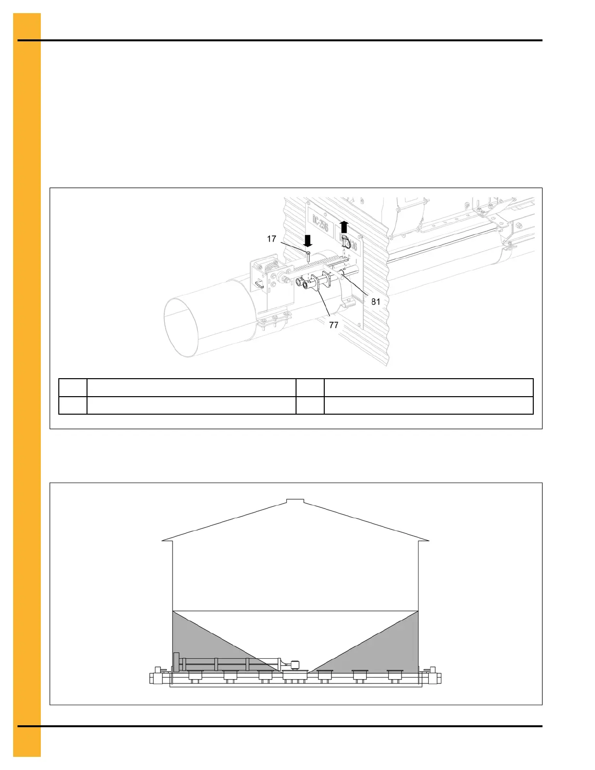
4. If the center well is jammed or if unable to open the center well gate, open the auxiliary well gate by
inserting the 5/16" x 1-1/2" HHCS bolt (17) through the rack and pinion (77) tube and auxiliary well
control rod (81). Open slowly while monitoring the grain flow to prevent plugging of the unload.
NOTE: Make sure to remove the 5/16" x 1-3/8" safety pin, that couples the auxiliary well control rod
with the intermediate well control rod (only the smaller diameter control rod should be
opened by the operator). The grain flow should look like as shown in Figure 4-5, page 60.
Figure 4-4 Opening the auxiliary well gate
17
5/16" x 1-1/2" HHCS bolt
81 Auxiliary well control rod
77
Rack and pinion assembly
Figure 4-5 Grain flow from the center well gate
60
PNEG-2308 Chain Loop Power Sweep