ANALOG CONTROL
131
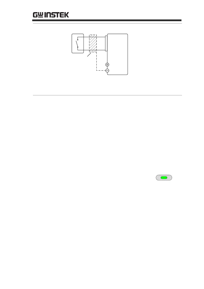
PSUSwitch
Analog
connector
20
19
Output
Terminal
2 core shielded
wire or twisted
pair
Pin19 → Switch
Pin20 → Switch
Wire shield → negative (-) output terminal
1. Connect the external switch according to the
connection diagrams above.
2. Set F-94 (External output logic) in
the power on configuration
settings to 0 (High = On) or 1 (Low
= On) and set F-98 (External output
control function) to 1(On).
Be sure to cycle the power after setting the
power on configuration settings.
3. Press the Function key and confirm
the new configuration settings
(F-94 = 0 or 1 and F-98=1).
4. The switch is now ready to set the output on or
off.
 Loading...


