COMMUNICATION INTERFACE
175
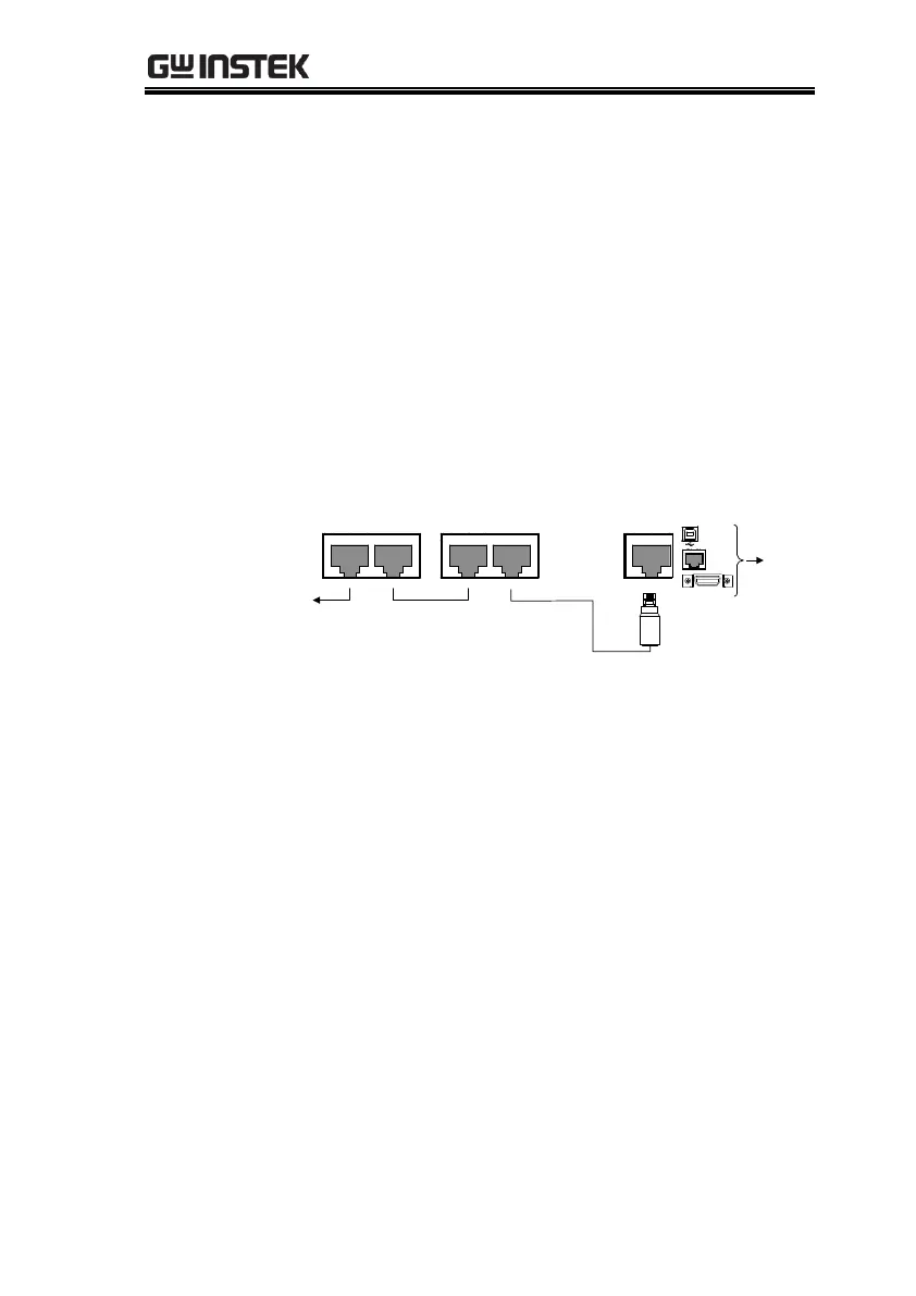
3. Connect the first unit’s LAN, USB or GPIB port
to a PC.
4. Plug in intermediate connector to the OUT port
on the first unit then using the master serial link
cable (gray plug) to connect intermediate
connector to the IN port of the second unit.
5. Connect all the remaining units between the
OUT port and the IN port with the slave serial
link cable (black plug) supplied in the PSU-232
or PSU-485 connection kit until all the desired
units have been daisy-chained together.
RS 485 / 232
OUT
Unit #1
RS 485 / 232
OUT IN
Unit #2
RS 485 / 232
OUT IN
Unit #N
End terminal
connector
To PC
Master serial link
cable (gray plug)
Slave serial link
cable (black plug)
USB
LAN
GPIB
Intermediate
connector
6. Terminate the OUT port of the last unit with the
end terminal connector included in the PSU-232
or PSU-485 connection kit.
7. Power up all slave units.
8. Set the addresses of all slave units using the
F-76 parameter.
Set the address of the unit. It must
be a unique address identifier.
9. Set the Multi-Drop setting parameter (F-77) to
Slave for all slave units.
Set the Multi-Drop setting to
slave.
10. Power up the master unit.
 Loading...


