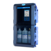
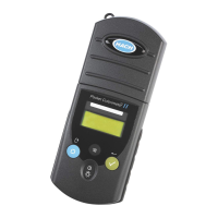
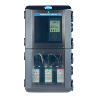
To drain all water from the instrument:
1. Remove the instrument from service.
2. Disconnect the instrument from the water system.
3. Set the power switch to on.
4. Push << to show the sliding menu.
5. Select Diagnostics>Tests>Plumbing Test.
6. From the drop-down menu, select Flow through cell with pump.
7. Let the test continue until all of the water has drained from the instrument.
8. When the water flow stops, push the green arrow to stop the plumbing test.
Send the instrument for service
C A U T I O N
Chemical exposure hazard. Dispose of chemicals and wastes in accordance with local, regional and
national regulations.
1. Drain the instrument. Refer to Drain the instrument on page
41.
2. Clean the instrument fully.
3. Get a return authorization from the manufacturer. Make sure that the return authorization number
is on the shipping label.
Troubleshooting
The analyzer incorporates extended diagnostic and reporting to inform the user about the nature of a
problem.
Alarm codes, with user-initiated diagnostic tests, serve to isolate the source of the problem. The
analyzer constantly monitors its operation and measurement values for alarm conditions.
Alarm conditions include error alarms, critical error alarms, warning alarms and measurement
alarms.
Alarms
Alarm indication
The analyzer has two basic operational modes: online and bottle. The online TOC and conductivity
are the two primary online modes. In online TOC and conductivity modes, the measurement screen
shows an animation that identifies the general state of water flow through the analyzer.
In online TOC, conductivity, or manual TOC modes, the animation area is also an alarm condition
indicator. When an alarm occurs in an online mode:
• The animation area flashes red.
• The value of the variable that has caused the alarm becomes red.
• The alarm sound
**
is heard if enabled.
• The alarm condition is recorded to the data log and audit trail.
• The alarm icon is enabled.
• Error, critical error or warning: The digital output that represents the error state identifies an error
condition. Refer to Configure the digital output alarms on page 31.
• Error or critical error: The three analog outputs identify an error condition (2 mA or 22 mA). Refer
to Configure the analog outputs on page 33.
**
Each type of alarm (stop, warning, alarm) has a different sound. If multiple alarms occur, only the
highest-level alarm is heard.
42 English
 Loading...
