Controls and display
27
TRIG / UNIT (Pushbutton)
Triggers a measurement in the manual trigger mode; se-
lection of a unit
28
AUTO / 6 (Pushbutton)
Selection of the automatic measurement function; numeric
key 6 when entering numeric parameters
29
M / – (Pushbutton)
Selection of the measurement function „Mutual Inductance“
(only with the appropriate cable set) or input of the character
„-“.
30
R-Q / 5 (Pushbutton)
Selection of the measurement function ‘Resistance‘ R und
‘Quality factor‘ Q; numeric key 5 when entering numeric
parameters
31
N-Θ / . (Pushbutton)
Selection of the measurement function ‘Turns ratio‘ N and
‘Phase angle‘
Θ; input of the character “. “ when entering
parameters
32
C-R / 4 (Pushbutton)
Selection of the measurement function ‘Capacitance‘ C
and ‘Resistance‘ R; numeric key 4 when entering numeric
parameters
33
G-B / 0 (Pushbutton)
Selection of the measurement function ‘Conductance‘ G
and ‘Susceptance‘ B; numeric key 0 when entering numeric
parameters
34
C-D / 3 (Pushbutton)
Selection of the measurement function ‘Capacitance‘ C and
‘Dissipation factor‘ D; numeric key 3 when entering numeric
parameters
35
R-X / 9 (Pushbutton)
Selection of the measurement function ‘Resistance‘ R and
‘Reactance‘ X; numeric key 9 when entering numeric para-
meters
36
L-R / 2 (Pushbutton)
Selection of the measurement function ‘Inductance‘ L and
‘Resistance‘ R; numeric key 2 when entering numeric pa-
rameters
37
Y-Θ / 8 (Pushbutton)
Selection of the measurement function ‘Admittance‘ Y and
‘Phase angle‘
Θ; numeric key 8 when entering numeric
parameters
38
L-Q / 1 (Pushbutton)
Selection of the measurement function ‘Inductance‘ and
‘Quality factor‘ Q; numeric key 1 when entering numeric
parameters
39
Z-Θ / 7 (Pushbutton)
Selection of the measurement function ‘Impedance‘ Z and
‘Phase angle‘
Θ; numeric key 7 when entering numeric
parameters
40
DISPLAY MODE (Pushbutton)
Toggles the display: measurement value with / without
parameters
41
RECALL / STORE (Pushbutton)
Saveandrecallofinstrumentcongurations(10memories)
42
REMOTE / LOCAL (Pushbutton)
Toggling between front panel and external operation; the
REMOTE/LOCAL pushbutton lights up if the instrument is
being addressed via the interface
47
(Remote Control). In
order to return to local control push REMOTE/LOCAL, pro-
vided the local control was not locked out via the interface
(local lockout). If local lockout was activated, the instrument
can not be operated from the front panel.
43
Ground (4 mm socket)
Ground connector (
). The socket is directly connected to
the mains safety ground!
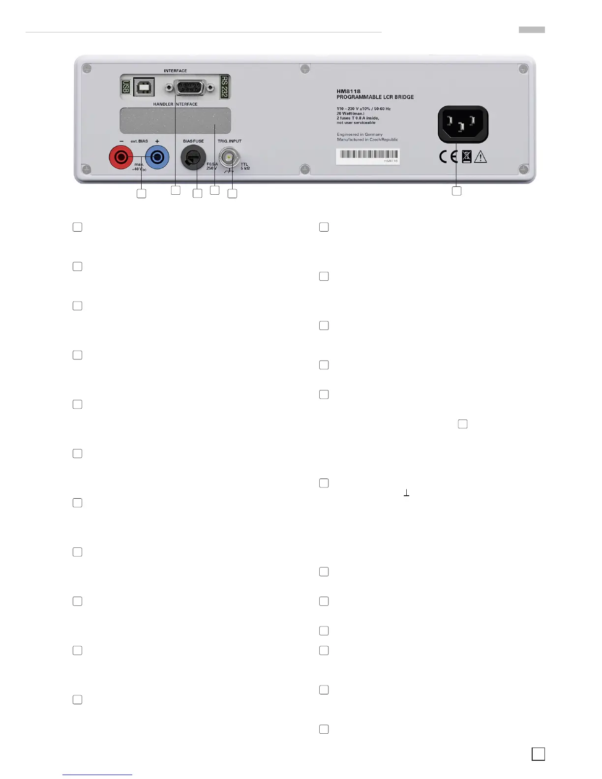
Rear panel
44
TRIG. INPUT (BNC socket)
Trigger input for external triggering
45
BIAS FUSE (Fuse holder)
Fuse for external voltage input ext. BIAS
46
ext. BIAS (4 mm safety sockets) External bias input (+, –)
47
INTERFACE
HO820 Dual Interface USB/RS-232 (galvanically isolated) is
provided as standard
48
HANDLER INTERFACE (25 pin D-Sub socket)
Output to control external binning sorters for components
(option HO118)
49
POWER INPUT (Power Cord Receptacle)
47 48
45
4446
49
 Loading...


