First-time operation
4.2 Turning on the instrument
Turn on the LCR bridge by
pressing the power switch
1
on the front panel. All
pushbuttons will light up for a
moment, then the instrument
will be ready to operate by
using the pushbuttons and
the knob. In case the push-
buttons and display do not
light up, either the mains
voltage is missing or any of the internal mains fuses are open
(see page 35). The actual measurement results are shown on
the right-hand side of the display, the most important para-
meters on the left-hand side. The components to be tested are
connected to the 4 BNC front panel connectors either directly
or using the appropriate accessories. A 4 mm banana jack is
also provided for a direct connection of the instrument to a
suitable ground potential.
Please note!
Unplug any test adapter or accessory for component
measurements by pulling straight towards you!
The front panel ground connector and the ground
contact of the trigger input are directly connected
to the mains safety ground potential through the
line cord. The outer contacts of the front panel
BNC connectors
20
–
23
(as well as the shields
of any coaxial cables attached) are connected to
the GUARD potential which has no connection to
the safety ground! No external voltages may be
applied to the BNC connectors! The rear panel
interfaces
47
and
48
are galvanically isolated (no
connection to ground)!
Ifthereareunidentiablemessagesonthe display,orifthe
instrument fails to react to operation of its controls: turn it
off, wait a minute and turn it on again in order to trigger a re-
set operation. If the display remains unchanged or operation
impossible,turnitoffandtakeittoaqualiedservicecentre.
(see page 35).
4.3 Line frequency
Prior to any measurements, the line frequency setting must be
set to the applied line frequency, 50 or 60 Hz. If the line frequency
is not set properly, depending on the measurement range and
the line frequency value, instabilities may occur e.g. on the
display. In order to set the line frequency press the SELECT
button
3
, use the SYST menu for accessing MAINS FRQ, use
the knob
6
for selecting the correct value.
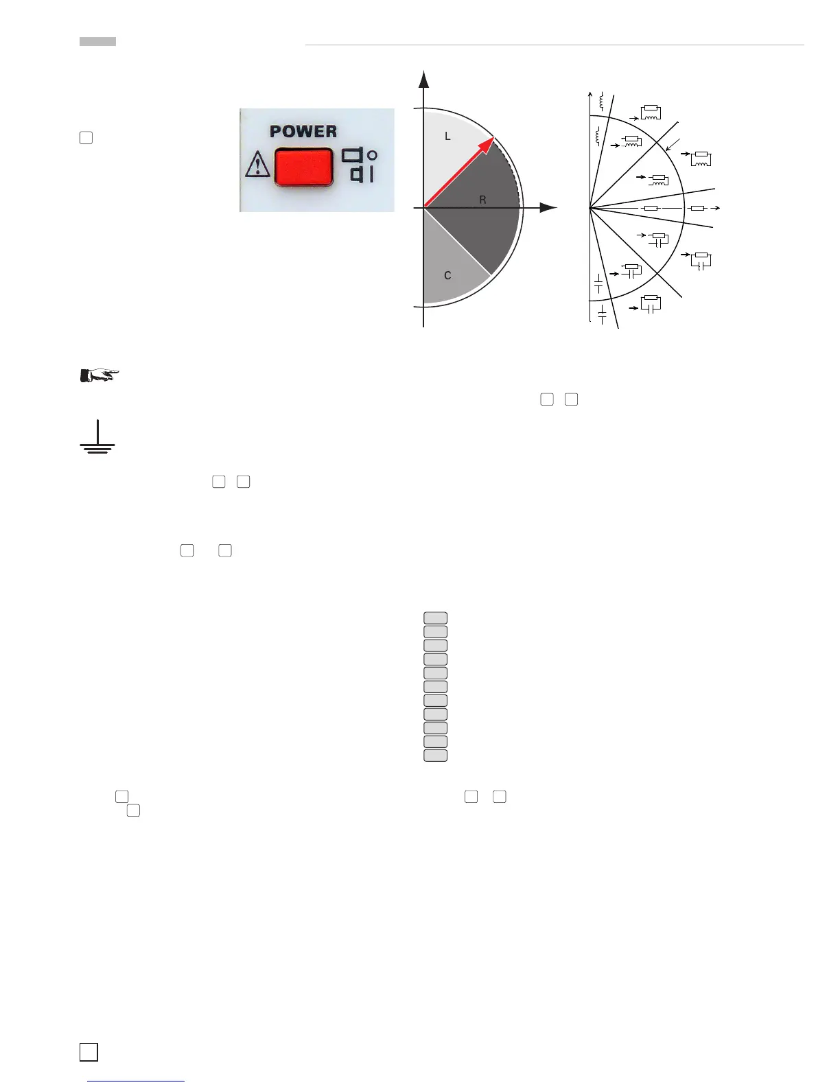
4.4 Measuring principle
In fact, it measures the impedance (|Z|) and the phase angle
(
Θ) of the device under test and, depending on the result,
the component willbe identiedaccording to the drawing
below.
Fig. 4.4: HM8118 Measuring Principle schematic left / detailed pre-
sentation right
In the automatic mode, the HM8118 selects the measurement
function (pushbuttons
28
–
39
) as such as well as the internal
equivalent circuit of the measurement circuit according to the
values measured, either serial (for inductive loads) or parallel
(for capacitive loads). See also chapter 4.8.
4.5 Main measurement and second measurement
value display
The LCR meter HM8118 is able to measure and display two
parameters simultaneously selected from 9 measurement
functions.Therstparameterisrelatedtothe„rstormain
measurement value display“ and the second parameter to the
„second measurement value display“. The following main- and
second measurement values can be displayed:
L-Q
Inductance L and quality factor Q
L-R
Inductance L and resistance R
C-D
Capacitance C and loss tangent D
C-R
Capacitance C and resistance R
R-Q
Resistance R and quality factor Q
Z-
Θ
Apparent impedance (admittance) Z and phase angle Θ
Y-
Θ
Apparent conductance Y and phase angle Θ
R-X
Resistance R and Reactance X
G-B
Conductance G and susceptance B
N-
Θ
Transformer turns ratio N and phase angle Θ
M
Transformer mutual inductance M
The measurement functions can be selected by pressing the
buttons
29
to
39
.
The actual measured series resistance includes all series re-
sistances such as the component leads and the resistance of
series-connected foils in capacitors as well as dielectric losses;
it is expressed by the dissipation factor DF. The equivalent
series resistance (ESR) is frequency-dependent according to
the formula:
ESR = Rs = D/
wCs
where
ω „Omega“ = 2 π f (circular frequency) represents.
Traditionally, the inductance of coils is measured in a series
circuit; however there are cases where a parallel circuit will
yield a better representation of the component. In small „air“
coils mostly the ohmic or copper losses are predominant , hence
the series circuit is the proper representation. The core of coils
with an iron or ferrite core may contribute most of the losses,
the parallel circuit is to prefer here.
Fig. 4.3: On/Off button
Imaginary
Axis
below -- 45° = C
above 45° = L
Real
Axis
phase angle
applied on the red terminal. The bias voltage works only
when the instrument on capacitance measurement
mode.
Measuring function selection
The desired test function is selected by push buttons (12)
and (14). The push button (12) gives access to the main
parameter (R, L or C), The push button (14) allows a
secondary parameter measurement (Q/D, impedance or
phase).
In order to measure D parameter the instrument needs at
first to be set to capacitance measurement mode, on the
other way, Q parameter will be displayed.
Auto-measurement function
The HM8018-2 is able to automatically determine the
component type in most cases. 3 different automatisms
exists: the automatic impedance range selection (see the
section « Auto-ranging»), the automatic mode
(series/parallel) selection (see the section « passive
components »), and the automatic function selection. These
three automatisms are simultaneously activated when the
instrument is set in automatic mode with the RANGE
AUTO key (7). Then the user can change function or mode
that disables their respective automatism. The manual range
selection disables the three automatisms.
When the instrument is on automatic mode the function
choice depends on the impedance module, phase angle as
well as the quality factor .The diagram below shows the
choice made by the instrument.
Calculation functions
Apart from displaying normal values as resistance, inductance or
capacitance, the HM8018-2 can display relative deviations and
percentages. It is not possible to use these calculation modes for
other functions than the three previous values. The deviations
and percentages are displayed in relation to the two stored values
A and B.
The procedure to obtain relative measurement is as follows:
1) Connect the component corresponding to the reference
value.
2) Store the value (memory A) by pressing on the STORE key,
then press the A key.
3) Press on the A key. The indicator -A lights up and the
display shows the value (Measure – A).
A direct percentage measurement is possible, it is only to use the
÷B key instead of the –A key in the previous procedure. Then the
instrument displays the value 100*Measure/B in %.
To obtain a deviation in % proceed as follows:
1) Connect the component corresponding to the reference
value.
 Loading...


