Connecting of components andmeasurement accessories
from 20 Hz to 200 kHz. The measurement adapter serves as
an interface between the LCR bridge and the 4 test associated
leads. According to the imprinted circuit diagram the transfor-
mer is connected on the primary and the secondary with the
test leads to the measurement adapter.
The LCR bridge displays no value for N if the mea-
surement is erroneous.
This accessory is not contained in shipment.
7.3.1 Specications
Functions: Measurement adapter for use
with LCR bridge HM8118 (via
4 wire connection)
Measurable components: Transformers
Measurable parameters: Mutual inductance M
(1µH...100H),
turns ratio N (0.95...500),
phase difference
φ
between
primary and secondary win-
dings (-180°...+180°)
Frequency range: 20Hz...200kHz
Measuring cable length about 35cm
Connectors: BNC plugs (4), BNC jacks (4)
Safety standards EN61010-1; IEC61010-1;
EN61010-031; IEC61010-031
Environmental conditions Degree of pollution 2, inten-
ded to use indoors
Operating temperature: +5°C...+40°C
Storage temperature: -20°C...+70°C
Weight: about 240g
7.3.2 Calibration
The measurement adapter HZ186, due to its construction,
has a stray capacitance, a residual inductance and a residual
resistance which impair the accuracy of the measurement
results.Inordertominimizetheseinfluencesitisnecessary
to compensate for impedance measurement errors caused by
the adapter and the leads.
To compensate for these measurement errors an OPEN and
a SHORT calibration should be performed at the LCR bridge
HM8118. The procedure was described in chapter 6 „Calibra-
tion“. The calibration values obtained during the calibration
procedure will be stored in the LCR bridge HM8118 and remain
valid until the next calibration.
For frequency depending components it is impor-
tant to perform an OPEN resp. SHORT calibration
for each of the 69 test frequencies.
For an OPEN calibration four test leads have to be connected
to the measurement adapter HZ186. Before starting the OPEN
calibration both black test leads, which are connected to the
„COMMON“ BNC jacks, have to be connected. The latter also
applies for both red test leads, which are connected to the BNC
jacks „N“ and „1“ (see Fig. 7.7). For a SHORT calibration both
red test leads have to be connected with the black test leads.
Fig. 7.7: OPEN / SHORT calibration with HZ186
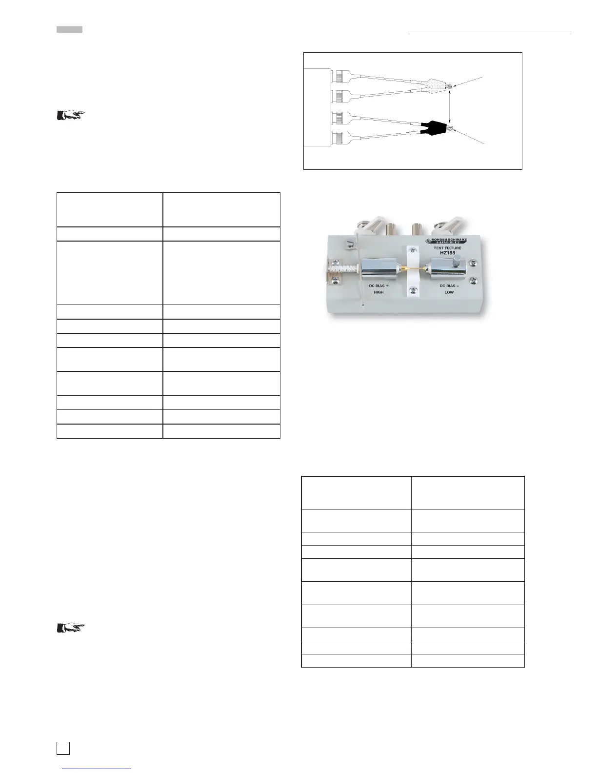
7.4 4 wire SMD test adapter HZ188
Fig. 7.8: 4 wire SMD test adapter HZ188
The SMD test adapter HZ188 is capable to qualify SMD com-
ponents. The test adapter converts a 4 wire measurement to a
2 wire measurement. Due to its own weight, the measurement
adapter and the measurement bridge should stand together on
a plane surface (a table for example). The measuring adapter
is connected directly with the 4 frontpanel BNC jacks. The
SMD component should be clamped between the two destined
contact pins (measuring contacts). This accessory is contained
in shipment.
7.4.1 Specications
Function: Test adapter for use with the
LCR bridge HM8118 (4-wire
connection)
Measurable components: SMD resistors, coils, capa-
citors
Frequency range: 20Hz...200kHz
Maximum voltage: ± 40 V maximum (AC+DC)
Connectors: BNC jacks (4), measuring
contacts (2)
Safety standards EN61010-1; IEC61010-1;
EN61010-031; IEC61010-031
Environmental conditions: Degree of pollution 2, inten-
ded for use indoors
Operating temperature: +5 °C ... +40 °C
Storage temperature: -20 °C ... +70 °C
Weight: about 300g
7.4.2 Calibration
The measurement adapter HZ188, due to its construction,
has a stray capacitance, a residual inductance and a residual
resistance which impair the accuracy of the measurement
Short Circuit
Short Circuit
Open
 Loading...


