Subject to change without notice
Connecting of components andmeasurement accessories
results.Inordertominimizetheseinfluencesitisnecessary
to compensate for impedance measurement errors caused by
the adapter and the leads.
To compensate for these measurement errors an OPEN and
a SHORT calibration should be performed at the LCR bridge
HM8118. The procedure was described in chapter 6 „Calibra-
tion“. The calibration values obtained during the calibration
procedure will be stored in the LCR bridge HM8118 and remain
valid until the next calibration.
For frequency depending components it is impor-
tant to perform an OPEN resp. SHORT calibration
for each of the 69 test frequencies.
In order to perform the SHORT calibration of the test adapter
HZ188, turn the screw on the righthand side CCW loose. Then
use the pushbutton to push the right contact pin to the left until
both contact pins are electrically connected. Then fasten the
rightcontactpinbyturningthescrewCW.(Seeg.7.9)
10
Änderungen vorbehalten
Für den „Kurzschlussabgleich“ ist bei dem Messadapter
HZ188 die Schraube auf der rechten Seite gegen den Uhr-
zeigersinn zu lösen und anschließend der rechte Kontaktstift
mit der Taste nach links zu drücken, bis beide Kontaktstifte
elektrisch verbunden sind. Danach ist der rechte Kontakt-
stift durch drehen der Schraube im Urzeigersinn zu xieren
(siehe Bild 2).
Bild 2 „Kurzschlußabgleich“
Screw
Locked
Lever
Fig. 7.9: SHORT circuit with HZ188
To perform an OPEN calibration turn the screw on the righthand
side CCW and push the right contact pin so far to the right that
both contact pins are apart. The distance between both pins
should equate the length of the SMD component to be mea-
sured.ThenfastenthescrewbyturningitCW(seeg.7.10).
10
Änderungen vorbehalten
Für den „Kurzschlussabgleich“ ist bei dem Messadapter
HZ188 die Schraube auf der rechten Seite gegen den Uhr-
zeigersinn zu lösen und anschließend der rechte Kontaktstift
mit der Taste nach links zu drücken, bis beide Kontaktstifte
elektrisch verbunden sind. Danach ist der rechte Kontakt-
stift durch drehen der Schraube im Urzeigersinn zu xieren
(siehe Bild 2).
Bild 2 „Kurzschlußabgleich“
Screw
Lever
Without SMD
Component
Fig. 7.10: OPEN calibration with HZ188
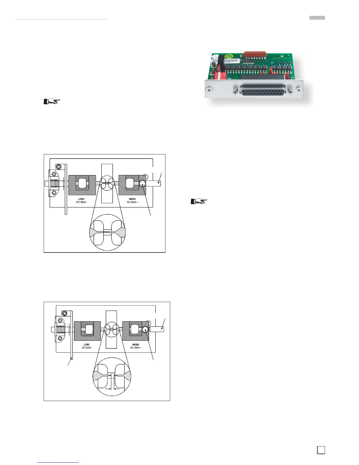
7.5 Option HO118 binning interface for
component sorting
Fig. 7.11: Optional accessory HO118 binning interface.
A bining interface (25-pin interface) is especially useful in a
production environment:
– for incoming inspection of components
– for the selection of components within tolerance limits
– and if frequently components of similar values have to be
tested.
The binning interface for the LCR bridge HM8118 allows opera-
tion with external hardware which sorts components according
to the measurement results of the HM8118. There are control
outputs for 8 BINs as well as further control outputs (ALARM,
INDEX, EOM, TRIG).
We recommend installing the HO118 at the factory
because the instrument has to be opened which would
entail the loss of warranty.
7.5.1 Specication
Output signal:
Negative TRUE, open collector, opto-isolated, selectable pull-
ups.
Measurement modes:
When the HM8118 is used for binning, the number of measure-
ment modes is limited to the necessary modes for characteri-
zing components. These modes can be selected:
– R-Q: Resistance-Quality factor
– C-D: Capacitance-Dissipation factor
– L-Q: Inductance-Quality factor
Kind and number of BINs:
– pass BINs: BIN 0...5 for primary parameters
– fail BINs: BIN 6 for secondary parameters, BIN 7 is destined
for general failures
– maximum current at an output voltage of 1 V is 15 mA (open
collector outputs)
Index:
Analog measurement complete
Measurement complete:
Measurement completed successfully.
Alarm:
Errornotication.
External trigger:
Opto-isolated, selectable pull-up, pulse width > 10µs.
Itispossibletosetup9binningcongurationswiththeSave/
Recallfunction.Thebinningcongurationsmayberemote-con-
Locked
 Loading...


